


Results 1 to 10 of 55
Hybrid View


-
12-10-2014, 01:16 PM #1Staff Engineer

- Join Date
- May 2014
- Location
- Highlands Ranch, Colorado USA
- Posts
- 1,437

Some general info for those just starting to look at the motion settings...
1. Watch the units. Assuming metric, g-code F parameters for feed rate on G1 commands are in mm/minute. Most of the Marlin settings are in mm/sec. Slicer units vary. I like the way some of the Marlin source code has the values for mm/minutes entered as, for example, 2*60. That helps one realize/remember that the setting is 2mm/sec, multiplied by 60 to come up with the value in mm/min.
2. Watch out for EEPROM settings. ABL folks are well aware of this issue, but if you have EEPROM enabled you can run into issues seeing the effect of changes you're making in source code. That's because the old EEPROM values will be used for settings even though you've loaded new firmware into the printer's flash memory. To update the EEPROM settings after a firmware upload, you should send the printer an M502 command to load the variable space with data from the firmware build, and then an M500 to have Marlin copy those variables into EEPROM.
3. Repetier-Host users, note the EEPROM access available through Config | Firmware EEPROM Configuration once RH is connected to the printer. This provides a way to view, edit and restore EEPROM data without having to browse through the LCD or deal with gcodes.
4. Mapping between configuration.h motion settings, the settings under the LCD control | motion menu, and settings via gcode is as follows:
HOMING_FEEDRATE {X,Y,Z,E} is not in the LCD menu tree. M210 in gcode but not supported in our Marlin.
DEFAULT_MAX_FEEDRATE {X,Y,Z,E} is Vmax x, Vmax y, Vmax z, and Vmax e on LCD. M203 in gcode.
DEFAULT_MAX_ACCELERATION {X,Y,Z,E} is Amax x, Amax y, Amax z, and Amax e on LCD. M201 in gcode.
DEFAULT_ACCELERATION is Accel on LCD. M204 S in gcode.
DEFAULT_RETRACT_ACCELERATION is A-retract on LCD. M204 T in gcode.
DEFAULT_XYJERK is vxy-jerk on LCD. M205 X in gcode.
DEFAULT_ZJERK is vz-jerk on LCD. M205 Z in gcode.
DEFAULT_EJERK is ve-jerk on LCD. M205 E in gcode.
DEFAULT_AXIS_STEPS_PER_UNIT is Xsteps/mm, Ysteps/mm, Zsteps/mm and Esteps/mm on LCD. M92 in gcode.
5. Note in the above list that every constant with a DEFAULT prefix also has a gcode associated with it. The DEFAULT label simply implies that will be the value used by the printer until it is superseded from the LCD or a gcode command.
6. There is a code limitation that kicks in when trying to use the LCD panel to edit the Amax z parameter. The code assumes the user will be selecting a number beginning with 100 and incrementing/decrementing by 100. Unfortunately, the MakerFarm default for Amax Z is 5. With the code the way it currently is, once you bring up the Amax Z screen, the value changes to 100 and you can't return it to 5. Stay out of the Amax Z menu item unless you want to adjust the value in increments of 100.
7. There's an order of precedence to some of the settings. DEFAULT_MAX_FEEDRATE sets the upper speed limit for the printer. Faster feed rates specified in MANUAL_FEEDRATE, HOMING_FEEDRATE, or a gcode command will be limited to the setting in DEFAULT_MAX_FEEDRATE. Only a new firmware build or the LCD will allow you to set a higher feed rate.Last edited by printbus; 12-31-2016 at 05:27 PM.
-
12-10-2014, 06:52 PM #2Engineer
- Join Date
- Jul 2014
- Location
- Eastern Colorado
- Posts
- 536
Huh, so that's what that was for. I'm dense. Originally Posted by printbus

-
12-14-2014, 12:27 AM #3Staff Engineer
- Join Date
- May 2014
- Location
- Highlands Ranch, Colorado USA
- Posts
- 1,437
A STAB AT CALCULATING A MAXIMUM PRINT SPEED
So far, we've put a lot of faith in the achievable step rate of 16 kHz stated in http://reprap.org/wiki/Step_rates. But configuration_adv.h has a MAX_STEP_FREQUENCY parameter defined to 40000. By label alone, it sounds like we should use 40 kHz instead of 16 kHz in our calculations, right?
MAX_STEP_FREQUENCY is used in setting up a timer value in stepper.cpp. Reading the code doesn't do well at suggesting what's going on here. I found M2 vs. Marlin: Speed Calculations and a comment in Makergear M2: Z Axis Numbers helpful. Up to a step rate of 10 kHz, Marlin will create stepper interrupts at the rate required. Over a 10 kHz step rate, Marlin keeps the timer interval at 10 kHz but starts combining two steps into each interrupt. Over a 20 kHz step rate, Marlin starts combining four steps into each interrupt interval. The references suggest combining steps in each interrupt can lead to jitter since the interval between steps won't be consistent.
So, one thought is to keep the step rate below 10 kHz to stay away from this jitter. Since we only care about this when we're printing, we don't need to worry about the reduced limit for Z-axis moves (well, maybe if you're printing spiral or with ABL but then the Z axis moves are slow). If the DEFAULT_MAX_FEEDRATE value for the extruder really only comes into play for retractions, we don't need to worry about the reduced limit there either. Nor with non-printing X-Y moves. So, we can tentatively leave DEFAULT_MAX_FEEDRATE alone and deal with the 10 kHz step rate as a limit on maximum print speed we use in the slicer instead.
Revisiting our feed rate equation for X and Y, the max print speed would = ( steps per second / steps per mm). Steps per mm was previously baselined to 80 for X and Y. Plugging in the numbers we get max print speed = ( 10,000 / 80 ) or 125 mm/second. So, ignoring an obvious question on whether the hot end can keep up and whether we need to adjust for stepping that has to also occur on the extruder motor while printing, we should be able to print perhaps up to 125 mm/sec before we risk picking up the jitter effects of handling motor steps in groups of two or four instead of individually. Why not add some margin and shoot for a max print speed of 100 mm/sec?
It's at least a place to start.Last edited by printbus; 12-21-2014 at 12:21 PM.
-
12-18-2014, 07:46 PM #4Staff Engineer
- Join Date
- May 2014
- Location
- Highlands Ranch, Colorado USA
- Posts
- 1,437
LET'S RECAP
- We've identified the key settings in configuration.h and configuration_adv.h pertinent to motion moves. Where applicable, we've shown the correlation between these settings, the settings on the LCD, and gcode commands available to manipulate them.
- We've identified a means to increase the speed of homing for the Z axis
- We've covered how the values in DEFAULT_STEPS_PER_UNIT are calculated for the X, Y, and Z axes
- Using the reprap wiki guideline of 16 kHz as a step rate limit, we've defined theoretically "achievable" values for DEFAULT_MAX_FEEDRATE of {200,200,5,17}. The "run hot" type stepper motors on at least my printer limit my Z feed rate to about 2.
- Using a more conservative 10 kHz step rate based on firmware insight, we've suggested 100-120 mm/sec as a top end on X Y print speeds to use in our slicer, reserving the theoretically achievable feed rates for use in travel moves.
- We've explored some gcode that allows us to see real-world effects of settings like DEFAULT_MAX_FEEDRATE, DEFAULT_MAX_ACCELERATION, and DEFAULT_RETRACT_ACCELERATION on our hardware. In addition to validating tentative settings, the gcode routines are handy in looking for vibrations or resonations, and even adjusting the current limit setting on the stepper motor driver boards.
We've also discussed how multiple settings can affect the same thing. There is an order of precedence between them -
- The settings loaded in the printer set the high/fast limit on feed rates. There are the DEFAULT_MAX_FEEDRATE settings in a firmware build or stored in the printer's EEPROM. Gcodes sent to the printer can only command settings lower/slower than the printer settings.
- Adjusting feed rate from the LCD has no such constraint. The LCD can be used to change a feed rate setting higher/faster than the installed firmware build or the current setting in EEPROM.
- For settings other than feed rates, gcode commands can be used to adjust settings both lower/slower and higher/faster than the respective DEFAULT value in the firmware build or EEPROM setting
- HOMING_FEEDRATE can only set speeds lower/slower than DEFAULT_MAX_FEEDRATE
- MANUAL_FEEDRATE for use with LCD commanded moves can only set speeds lower/slower than DEFAULT_MAX_FEEDRATE
- DEFAULT_MAX_ACCELERATION applies to to X, Y, Z. The E term applies only to extrusions while moving. DEFAULT_RETRACT_ACCELERATION is applied to the extruder for retraction and replenish filament-only moves.
- And here's the new point for this post. Acceleration factors for X, Y, Z and E moving extrusions are limited to the lower term in either DEFAULT_MAX_ACCELERATION or DEFAULT_ACCELERATION. DEFAULT_MAX_ACCELERATION simply allows you to manipulate each axis individually. If DEFAULT_MAX_ACCELERATION is set high enough, you can manipulate them all lower through a single setting or gcode command using DEFAULT_ACCELERATION. What happens in a retraction and subsequent recovery is not affected by this, since they are controlled by DEFAULT_RETRACT_ACCELERATION
The jerk settings are the motion settings we haven't addressed yet. And then we need to see how the feed rate, acceleration, and jerk settings all tie together.
HOMEWORK AND INDIVIDUAL STUDY
Gcode M204 Sx is the command for setting DEFAULT_ACCELERATION, where x is the acceleration value you want in mm/sec per second. Go back to some of the gcode exercises where the M201 command was used to manipulate acceleration factors for individual axes. Add an adjacent row for the M204 Sx command, observing which takes precedence over the other based on the value given to each.Last edited by printbus; 12-21-2014 at 12:38 PM.
-
12-21-2014, 02:05 PM #5Staff Engineer
- Join Date
- May 2014
- Location
- Highlands Ranch, Colorado USA
- Posts
- 1,437
As the thread starter, I'm hoping we don't have to continue the discussion on speed vs velocity, angular acceleration, etc. Mjolinor makes a technically valid point, but I believe the context of the comment goes beyond the current scope of the thread. Everything being discussed in this thread has been, and at least in my foreseeable future posts, will continue to be predominantly in the context of linear movements of the printer axes.
As Abumaia points out, an axis can only move linearly. It is the move planner that decides how to accomodate the possibly complex gcode commands as linear movements in X, Y, Z and the extruder, based on the axis constraints it has been given to work with. I am sure it is this three dimensional planning that forces the complexity into the move planning code. Ignoring the totality of that complexity in this thread is likely over-simplifying things, but I don't believe it is a flawed approach. Once we have some fundamentals covered, it may very well be interesting to know more about how Marlin applies constraints for the independent axes into move planning for more complex objects.
My plan has been to better understand the printer mechanics in a simple linear sense where I can easily visualize, demonstrate, see and feel the differences settings can make. Based on what I learned, I then froze the printer with some new settings so I could see whether they negatively affect the printing of real objects. This is where I'm at now. I would have rather been just trying settings someone else offered, but as of yet that option hasn't been made available. Personally, that's what I find the most frustrating about having to dig into the details.
Under the realm of possibility that there's just a difference between the US and UK on layman context regarding the term speed, I did go back through the thread and adjust how and where I had used it. I'm hoping I got it close enough and we can just leave it at that.Last edited by printbus; 12-22-2014 at 12:14 PM.
-
02-10-2015, 04:41 PM #6Staff Engineer
- Join Date
- May 2014
- Location
- Highlands Ranch, Colorado USA
- Posts
- 1,437
RIPPLE INVESTIGATION - PART ONE
This is an extension of the discussion that started in thread so what causes this. The thread questions what causes the ringing or ripple appearance often occurring at sharp corners, as well as following dimples, lettering, or other recesses in printed objects. Part one lays a foundation for discussing the theories, test prints, and results. Part two will get into the latter.
So, I opted to run some test prints to investigate possible causes and improvements, with a focus on how the Marlin motion related settings can come into play.
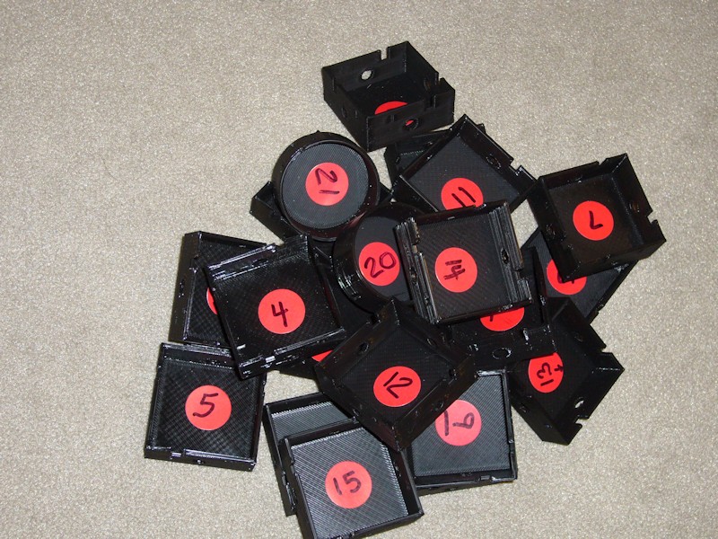
The information here is provided under the FWIW caveat. There's no solid, clear-cut miracle fix proposed, so don't read on expecting one. I'm only documenting the thoughts I've had on causes and the tests performed to prove them out. Perhaps the results here will spur ideas for someone to pursue on their own.
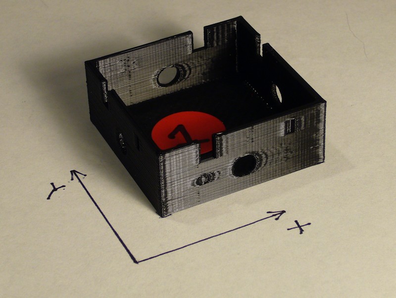
THE TEST OBJECT
A special test model was prepared for the testing in order to provide the mixture desired. The 45mm sides enables a high speed to be reached mid-perimeter. Corners are intentionally sharp 90 degree turns without any radius. All four sides include a combination of a round dimple, a recessed thin rectangle, a through-hole, and a rectangular notch at the top edge. Walls are 1.75mm thick. The depth of dimples and recesses vary.
An attempt was also made at a cylindrical test object, but the results were not conclusive and wouldn't photograph well. Results from the cylindrical prints will not be addressed.
The STL for the custom test object is available at http://www.thingiverse.com/thing:678295
THE TEST PRINTER
General details regarding the MakerFarm i3v 8-inch printer used for test prints can be found in my build thread at MakerFarm 8" i3v Prusa build by Printbus. The X and Y belts are currently adjusted tight to the point of being "pluckable". All hardware is tight. There's no slop in how the Y-bed rides on the Y-rails, the X-carriage carriage rides on the Z-rails, or the extruder carriage rides on the X-rails. The printer is equipped with six Sorbothane Duro-70 feet, and rests on 3/4-inch plywood. Wood 1/2-inch reinforcement plates have been added to the front and rear frame braces that support the ends of the Y-rails. Stepper motor drivers are adjusted for suitable operation of the motors, not to a particular current limit voltage setting.
The extruder is equipped with a 1.75mm hexagon hot end with a 0.40mm nozzle. The hexagon hot end is mounted snug in the extruder/carriage assembly. The hot end is snug in the extruder/carriage assembly; there is no slop or play in the nozzle.
BASELINE SETTINGS
MakerFarm black 1.75mm PLA purchased several months ago was used at the start of the test; I have considered this to be my premium filament because of resulting print quality. Unfortunately, I ran out of that filament after I ended up printing more tests than I anticipated. The second roll was a newer purchase of MakerFarm black 1.70 PLA that doesn't print as nicely. Black filament was used in order to facilitate photographing print artifacts.
Simplify3D v2.2.1 was used for all slicing related to these tests. The following scroll box contains details and notes regarding the "baseline" Marlin and Simplify3D settings for the testing. Many of these settings leverage values determined earlier in this thread. Note that the box is simply commented text. It is not an INI or other settings file that can be downloaded and used as-is. The settings are discussed in the sequence that they appear in the Simplify3D user interface. The settings are not intended to define the "perfect" settings for Simplify3D. They *only* define a standardized baseline configuration referenced in the print tests.
Printing of these tests followed experimenting with Simplify3D and a single-wall calibration print. Unfortunately, the setting of a manual extrusion width of 0.39mm was inadvertently also applied to initial ripple test prints. For consistency, this inadvertent setting was left intact through all test prints.
Code:Ripple Test Print configuration summary 21 Jan 2015 *** MARLIN DETAILS *** dacb fork for MakerFarm as of Sept 28 2014; personalized motion related changes: HOMING_FEEDRATE {100*60, 100*60, 2.5*60, 0} marlin_main.cpp homeaxis() feedrate in 3rd phase of homing reduced from /2 to /4 to negate faster HOMING_FEEDRATE DEFAULT_AXIS_STEPS_PER_UNIT {80, 80, 1000, 900} (Z motor driver configured for 1/4 microstepping) DEFAULT_MAX_FEEDRATE {250, 250, 3, 15} (3 on Z works with Kysan motors and 1/4 microstepping) DEFAULT_MAX_ACCELERATION {750,750,500,500} DEFAULT_ACCELERATION 750 DEFAULT_ZJERK 10 DEFAULT_EJERK 10 MANUAL_FEEDRATE {100, 100, 2.5, 5} *** Simplify3D v2.2.1 Process Settings - Extruder Nozzle diameter: 0.40mm Extrusion multiplier: 1.00 Extrusion width: Manually set to 0.39mm (see post) Retraction box: checked Retraction distance: 1.80mm Extra restart distance: 0mm Retraction vertical lift: 0mm Retraction speed: 15mm/sec (to match 15mm/sec setting in Marlin DEFAULT_MAX_FEEDRATE) Coast at end: checked and set to 1.6mm Wipe at end: unchecked and set to 5mm *** Simplify3D v2.2.1 Process Settings - Layer Primary layer height: 0.20mm Top solid layers: 3 Bottom solid layers: 3 Outline/perimeter shells: 2 Outline direction: Outside-in Print islands sequentially: unchecked Corkscrew printing mode: unchecked First layer height: 90% First layer width: 125% First layer speed: 50% Start points: use random start points for all perimeters *** Simplify3D v2.2.1 Process Settings - Additions Include skirt brim: checked Skirt layers: 1 Skirt offset: 4mm Skirt outlines: 3 Include raft: unchecked *** Simplify3D v2.2.1 Process Settings - Infill External fill pattern: rectilinear Interior fill percentage: 20% Outline overlap: 15% Infill extrusion width: 100% Minimum infill length: 5mm Print sparse infill every 1 layer Include solid diaphragm: unchecked Random infill placement: unchecked Infill angles: 45, -45 degrees *** Simplify3D v2.2.1 Process Settings - Support Generate support material: unchecked Support extruder: Primary Support infill percentage: 30% Extra inflation distance: 0 Dense support layers: 0 Dense infill percentage: 70% Print support every 1 layer Horizontal offset from part: 0.50mm Upper vertical separation layers: 1 Lower vertical separation layers: 1 *** Simplify3D v2.2.1 Process Settings - Temperature Extruder temperature identifier: T0 Extruder temperature controller type: Extruder Extruder relay temperature between each: (neither layer or loop selected) Extruder wait for temperature controller to stabilize: checked Extruder layer 1 temperature: 220 degrees Heated bed temperature identifier: T2 Heated bed temperature controller type: heated build platform Heated bed relay temperature between each: (neither layer or loop selected) Heated bed wait for temperature controller to stabilize: checked Heated bed layer 1 temperature: 55 *** Simplify3D v2.2.1 Process Settings - Cooling Layer 1 fan speed: 0 Blip fan to full power when increasing from idle: unchecked Adjust print speed for layers below set duration: unchecked Increase fan speed for layers below set duration: unchecked Bridging fan speed override: unchecked *** Simplify3D v2.2.1 Process Settings - G-code Option for 5D firmware: checked Option for relative extrusion distances: unchecked Option to allow zeroing of extrusion distances: checked Option to use independent extruder axes: unchecked Option to include M101/M102/M103 commands: unchecked Option for firmware supporting sticky parameters: checked G-Code axis offsets all set to 0 Update machine definition using settings: checked Machine type: Cartesian Build volume: 200mm x 200mm x 200mm (printer dependent) Origin offset: 0, 0, 0 Homing direction: all set to min Flip build table axis: Y checked *** Simplify3D v2.2.1 Process Settings - Other Default printing speed: 100 mm/sec (6000mm/min) Outline underspeed: 50% Solid fill underspeed: 80% Support structure underspeed: 80% X/Y axis movement speed: 250 mm/sec (to match setting in DEFAULT_MAX_FEEDRATE) Z axis movement speed: 2.5 mm/sec (to match setting in DEFAULT_MAX_FEEDRATE) Filament diameter: 1.68mm Bridging unsupported area threshold: 50 sq mm Bridging extrusion multiplier: 100% Bridging speed multiplier: 100% *** Simplify3D v2.2.1 Process Settings - Advanced Start printing at set height: unchecked Stop printing at set height: unchecked Non-manifold segments: heal Merge all outlines into solid model: unchecked Thin wall behavior: Allow gap fill when necessary Allowed perimeter overlap: 10% Only retract when crossing open spaces: checked Force retraction between layers: checked Minimum travel for retraction: 2mm Extruder ooze rate: unchecked Only wipe extruder for outer-most perimeters: checked Tool change retraction: settings ignored since I only have one extruderLast edited by printbus; 05-02-2015 at 09:16 PM. Reason: migrated to offsite image storage due to 3DPrintBoard issues


 Reply With Quote


Please explain to me how to...
05-17-2024, 12:15 PM in 3D Printer Parts, Filament & Materials