


Results 1 to 10 of 55
Threaded View


-
02-10-2015, 04:41 PM #11Staff Engineer

- Join Date
- May 2014
- Location
- Highlands Ranch, Colorado USA
- Posts
- 1,437

RIPPLE INVESTIGATION - PART ONE
This is an extension of the discussion that started in thread so what causes this. The thread questions what causes the ringing or ripple appearance often occurring at sharp corners, as well as following dimples, lettering, or other recesses in printed objects. Part one lays a foundation for discussing the theories, test prints, and results. Part two will get into the latter.
So, I opted to run some test prints to investigate possible causes and improvements, with a focus on how the Marlin motion related settings can come into play.
The information here is provided under the FWIW caveat. There's no solid, clear-cut miracle fix proposed, so don't read on expecting one. I'm only documenting the thoughts I've had on causes and the tests performed to prove them out. Perhaps the results here will spur ideas for someone to pursue on their own.
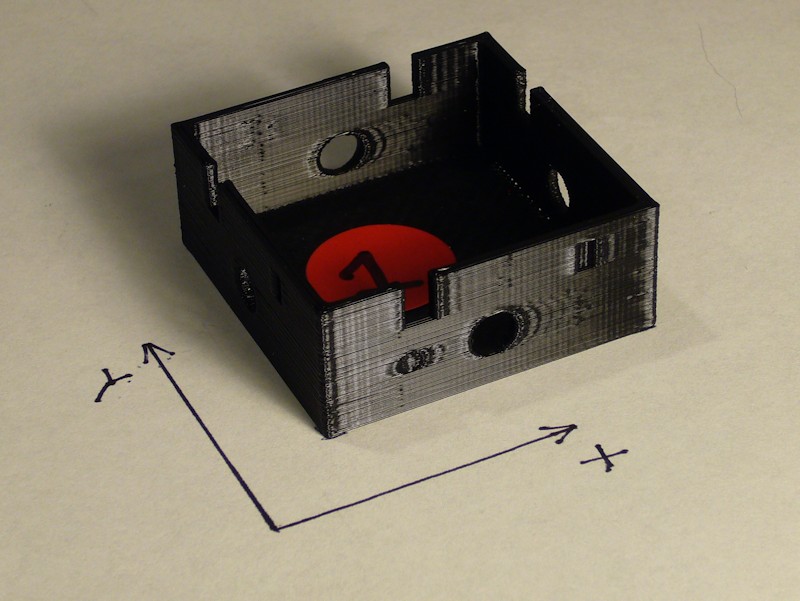
THE TEST OBJECT
A special test model was prepared for the testing in order to provide the mixture desired. The 45mm sides enables a high speed to be reached mid-perimeter. Corners are intentionally sharp 90 degree turns without any radius. All four sides include a combination of a round dimple, a recessed thin rectangle, a through-hole, and a rectangular notch at the top edge. Walls are 1.75mm thick. The depth of dimples and recesses vary.
An attempt was also made at a cylindrical test object, but the results were not conclusive and wouldn't photograph well. Results from the cylindrical prints will not be addressed.
The STL for the custom test object is available at http://www.thingiverse.com/thing:678295
THE TEST PRINTER
General details regarding the MakerFarm i3v 8-inch printer used for test prints can be found in my build thread at MakerFarm 8" i3v Prusa build by Printbus. The X and Y belts are currently adjusted tight to the point of being "pluckable". All hardware is tight. There's no slop in how the Y-bed rides on the Y-rails, the X-carriage carriage rides on the Z-rails, or the extruder carriage rides on the X-rails. The printer is equipped with six Sorbothane Duro-70 feet, and rests on 3/4-inch plywood. Wood 1/2-inch reinforcement plates have been added to the front and rear frame braces that support the ends of the Y-rails. Stepper motor drivers are adjusted for suitable operation of the motors, not to a particular current limit voltage setting.
The extruder is equipped with a 1.75mm hexagon hot end with a 0.40mm nozzle. The hexagon hot end is mounted snug in the extruder/carriage assembly. The hot end is snug in the extruder/carriage assembly; there is no slop or play in the nozzle.
BASELINE SETTINGS
MakerFarm black 1.75mm PLA purchased several months ago was used at the start of the test; I have considered this to be my premium filament because of resulting print quality. Unfortunately, I ran out of that filament after I ended up printing more tests than I anticipated. The second roll was a newer purchase of MakerFarm black 1.70 PLA that doesn't print as nicely. Black filament was used in order to facilitate photographing print artifacts.
Simplify3D v2.2.1 was used for all slicing related to these tests. The following scroll box contains details and notes regarding the "baseline" Marlin and Simplify3D settings for the testing. Many of these settings leverage values determined earlier in this thread. Note that the box is simply commented text. It is not an INI or other settings file that can be downloaded and used as-is. The settings are discussed in the sequence that they appear in the Simplify3D user interface. The settings are not intended to define the "perfect" settings for Simplify3D. They *only* define a standardized baseline configuration referenced in the print tests.
Printing of these tests followed experimenting with Simplify3D and a single-wall calibration print. Unfortunately, the setting of a manual extrusion width of 0.39mm was inadvertently also applied to initial ripple test prints. For consistency, this inadvertent setting was left intact through all test prints.
Code:Ripple Test Print configuration summary 21 Jan 2015 *** MARLIN DETAILS *** dacb fork for MakerFarm as of Sept 28 2014; personalized motion related changes: HOMING_FEEDRATE {100*60, 100*60, 2.5*60, 0} marlin_main.cpp homeaxis() feedrate in 3rd phase of homing reduced from /2 to /4 to negate faster HOMING_FEEDRATE DEFAULT_AXIS_STEPS_PER_UNIT {80, 80, 1000, 900} (Z motor driver configured for 1/4 microstepping) DEFAULT_MAX_FEEDRATE {250, 250, 3, 15} (3 on Z works with Kysan motors and 1/4 microstepping) DEFAULT_MAX_ACCELERATION {750,750,500,500} DEFAULT_ACCELERATION 750 DEFAULT_ZJERK 10 DEFAULT_EJERK 10 MANUAL_FEEDRATE {100, 100, 2.5, 5} *** Simplify3D v2.2.1 Process Settings - Extruder Nozzle diameter: 0.40mm Extrusion multiplier: 1.00 Extrusion width: Manually set to 0.39mm (see post) Retraction box: checked Retraction distance: 1.80mm Extra restart distance: 0mm Retraction vertical lift: 0mm Retraction speed: 15mm/sec (to match 15mm/sec setting in Marlin DEFAULT_MAX_FEEDRATE) Coast at end: checked and set to 1.6mm Wipe at end: unchecked and set to 5mm *** Simplify3D v2.2.1 Process Settings - Layer Primary layer height: 0.20mm Top solid layers: 3 Bottom solid layers: 3 Outline/perimeter shells: 2 Outline direction: Outside-in Print islands sequentially: unchecked Corkscrew printing mode: unchecked First layer height: 90% First layer width: 125% First layer speed: 50% Start points: use random start points for all perimeters *** Simplify3D v2.2.1 Process Settings - Additions Include skirt brim: checked Skirt layers: 1 Skirt offset: 4mm Skirt outlines: 3 Include raft: unchecked *** Simplify3D v2.2.1 Process Settings - Infill External fill pattern: rectilinear Interior fill percentage: 20% Outline overlap: 15% Infill extrusion width: 100% Minimum infill length: 5mm Print sparse infill every 1 layer Include solid diaphragm: unchecked Random infill placement: unchecked Infill angles: 45, -45 degrees *** Simplify3D v2.2.1 Process Settings - Support Generate support material: unchecked Support extruder: Primary Support infill percentage: 30% Extra inflation distance: 0 Dense support layers: 0 Dense infill percentage: 70% Print support every 1 layer Horizontal offset from part: 0.50mm Upper vertical separation layers: 1 Lower vertical separation layers: 1 *** Simplify3D v2.2.1 Process Settings - Temperature Extruder temperature identifier: T0 Extruder temperature controller type: Extruder Extruder relay temperature between each: (neither layer or loop selected) Extruder wait for temperature controller to stabilize: checked Extruder layer 1 temperature: 220 degrees Heated bed temperature identifier: T2 Heated bed temperature controller type: heated build platform Heated bed relay temperature between each: (neither layer or loop selected) Heated bed wait for temperature controller to stabilize: checked Heated bed layer 1 temperature: 55 *** Simplify3D v2.2.1 Process Settings - Cooling Layer 1 fan speed: 0 Blip fan to full power when increasing from idle: unchecked Adjust print speed for layers below set duration: unchecked Increase fan speed for layers below set duration: unchecked Bridging fan speed override: unchecked *** Simplify3D v2.2.1 Process Settings - G-code Option for 5D firmware: checked Option for relative extrusion distances: unchecked Option to allow zeroing of extrusion distances: checked Option to use independent extruder axes: unchecked Option to include M101/M102/M103 commands: unchecked Option for firmware supporting sticky parameters: checked G-Code axis offsets all set to 0 Update machine definition using settings: checked Machine type: Cartesian Build volume: 200mm x 200mm x 200mm (printer dependent) Origin offset: 0, 0, 0 Homing direction: all set to min Flip build table axis: Y checked *** Simplify3D v2.2.1 Process Settings - Other Default printing speed: 100 mm/sec (6000mm/min) Outline underspeed: 50% Solid fill underspeed: 80% Support structure underspeed: 80% X/Y axis movement speed: 250 mm/sec (to match setting in DEFAULT_MAX_FEEDRATE) Z axis movement speed: 2.5 mm/sec (to match setting in DEFAULT_MAX_FEEDRATE) Filament diameter: 1.68mm Bridging unsupported area threshold: 50 sq mm Bridging extrusion multiplier: 100% Bridging speed multiplier: 100% *** Simplify3D v2.2.1 Process Settings - Advanced Start printing at set height: unchecked Stop printing at set height: unchecked Non-manifold segments: heal Merge all outlines into solid model: unchecked Thin wall behavior: Allow gap fill when necessary Allowed perimeter overlap: 10% Only retract when crossing open spaces: checked Force retraction between layers: checked Minimum travel for retraction: 2mm Extruder ooze rate: unchecked Only wipe extruder for outer-most perimeters: checked Tool change retraction: settings ignored since I only have one extruderLast edited by printbus; 05-02-2015 at 09:16 PM. Reason: migrated to offsite image storage due to 3DPrintBoard issues


 Reply With Quote


New to 3d printing looking for...
05-20-2024, 12:56 AM in Tips, Tricks and Tech Help