Results 21 to 30 of 32
-
06-30-2017, 11:24 PM #21
If you had a RAMPS board I could tell you where to put the volt meter and what to crank the numbers up to. But most electronics boards let you control the stepper motor current. You can crank that up a lot and not worry about hurting the motors. As long as you can hold them in your hand for 10 or 15 seconds and not burn yourself, they are fine. If turning up the power doesn't fix the stuttering, slow down the max feed rate and acceleration numbers. For sure... You can make it move nicely and not lose position.
-
07-01-2017, 12:05 PM #22Student

- Join Date
- Jul 2016
- Posts
- 43
Stuttering was because of a failing solder I did - fixed.
Lead Screws needed new base plates printed to hold the Z Motors like 2mm further away from the frame than the threaded rods base plates - fixed. (This could have been avoided had I just read it twice before attempting the fix lol).
Was having filament getting stuck in the hot end issues due to heat creep - my fan wasn't turning on - fixed.
Man this list of tiny issues when just wanting to upgrade to dual extrusion lol.
Now onto printing a test cube with the new parts installed and then UBL!
-
07-02-2017, 10:35 PM #23Student

- Join Date
- Jul 2016
- Posts
- 43
Prints just fine with a single nozzle. Now I'd like to get UBL working to make things even better but I keep having issues.
It attempted to probe off the plate...
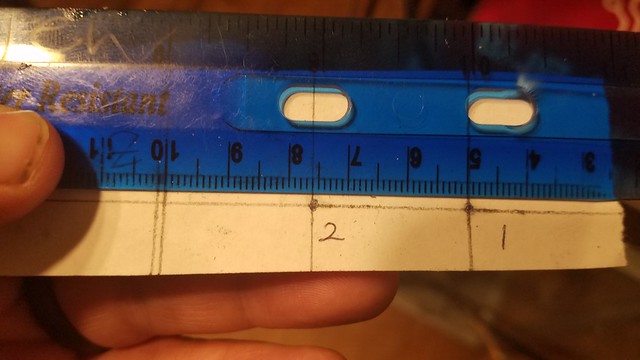
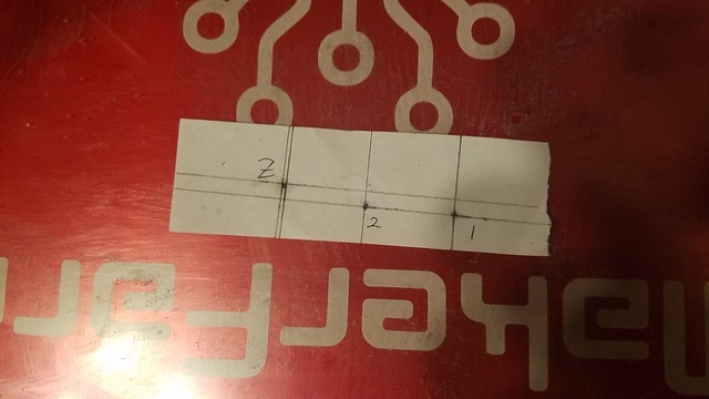
To get my Z probe settings I placed a small amount of grease on each nozzle and the tip of the probe. I then pressed that into a piece of paper and using a straight edge drew the lines. Using those lines I found that my probe is 50mm to the left of my main extruder and the 25mm to the left of my second one (so they are separated by 25 also convinently enough). It was also measured to be exactly 5mm behind the extruders.
So after that I had to make the points look like this to get the sketch to compile and upload to the printer.Code:#define X_PROBE_OFFSET_FROM_EXTRUDER 50 // X offset: -left +right [of the nozzle] #define Y_PROBE_OFFSET_FROM_EXTRUDER -5 // Y offset: -front +behind [the nozzle] #define Z_PROBE_OFFSET_FROM_EXTRUDER -0.65 // Z offset: -below +above [the nozzle]
Code://=========================================================================== //========================= Unified Bed Leveling ============================ //=========================================================================== #define UBL_MESH_INSET 1 // Mesh inset margin on print area #define GRID_MAX_POINTS_X 10 // Don't use more than 15 points per axis, implementation limited. #define GRID_MAX_POINTS_Y GRID_MAX_POINTS_X #define UBL_PROBE_PT_1_X 60 // These set the probe locations for when UBL does a 3-Point leveling #define UBL_PROBE_PT_1_Y 200 // of the mesh. #define UBL_PROBE_PT_2_X 60 #define UBL_PROBE_PT_2_Y 20 #define UBL_PROBE_PT_3_X 200 #define UBL_PROBE_PT_3_Y 20 #define UBL_G26_MESH_EDITING // Enable G26 mesh editing #elif ENABLED(MESH_BED_LEVELING)
Any help in this department would be greatly appreciated.
-
07-02-2017, 11:37 PM #24
What happens when you do a G29 P1 ? If it completes, do a G29 T and post the results. The 50mm X_PROBE_OFFSET_FROM_EXTRUDER is rather extreme. But depending on what we see in the T opography map, there are a number of ways to deal with the unprobed areas of the bed.
-
07-03-2017, 01:57 AM #25Student

- Join Date
- Jul 2016
- Posts
- 43
50mm seems odd to me as well considering Clough32 says it should be something like 27 on the Itty Bitty Flex Dual Extruder... BUT when I measured it said 50 on the nose.
I switched my settings back to mostly the same after finding the offsets in the configuration_adv.h:
Still using this bit:
Changed this back to the 3 points that are just barely inside the range:Code:#define X_PROBE_OFFSET_FROM_EXTRUDER 50 // X offset: -left +right [of the nozzle] #define Y_PROBE_OFFSET_FROM_EXTRUDER -5 // Y offset: -front +behind [the nozzle] #define Z_PROBE_OFFSET_FROM_EXTRUDER -0.65 // Z offset: -below +above [the nozzle]
And then changed on the advanced page:Code://=========================================================================== //========================= Unified Bed Leveling ============================ //=========================================================================== #define UBL_MESH_INSET 1 // Mesh inset margin on print area #define GRID_MAX_POINTS_X 10 // Don't use more than 15 points per axis, implementation limited. #define GRID_MAX_POINTS_Y GRID_MAX_POINTS_X #define UBL_PROBE_PT_1_X 55 // These set the probe locations for when UBL does a 3-Point leveling #define UBL_PROBE_PT_1_Y 180 // of the mesh. #define UBL_PROBE_PT_2_X 55 #define UBL_PROBE_PT_2_Y 20 #define UBL_PROBE_PT_3_X 180 #define UBL_PROBE_PT_3_Y 20 #define UBL_G26_MESH_EDITING // Enable G26 mesh editing #elif ENABLED(MESH_BED_LEVELING)
Code:#define UBL_MESH_MIN_X (X_MIN_POS + (UBL_MESH_INSET + 10)) #define UBL_MESH_MAX_X (X_MAX_POS - ((UBL_MESH_INSET - 10)))
Using this setup I ran the G29 P1 (and subsequently G29 T) to get this map:
Bed Topography Report:
(0,9) (9,9)
(11,309) (309,309)
. . . . . . . . . .
. . 0.360 0.262 0.132 0.038 -0.118 -0.242 -0.430 .
. . 0.352 0.248 0.105 -0.020 -0.170 -0.317 -0.538 .
. . 0.360 0.240 0.080 -0.077 -0.247 -0.407 -0.607 .
. . 0.428 [ 0.230] 0.067 -0.102 -0.287 -0.477 -0.713 .
. . 0.357 0.200 0.045 -0.130 -0.327 -0.518 -0.740 .
. . 0.367 0.225 0.040 -0.145 -0.345 -0.550 -0.810 .
. . 0.367 0.212 0.020 -0.165 -0.402 -0.615 -0.865 .
. . 0.395 0.202 -0.002 -0.212 -0.415 -0.667 -0.930 .
. . 0.390 0.197 -0.030 -0.220 -0.495 -0.740 -1.027 .
(11,1) (309,1)
(0,0) (9,0)
-
07-03-2017, 09:02 AM #26
You have a 1.0 mm tilt from left to right. UBL can handle that. But you will get better results if you physically level your bed. You can use G29 P1 U T to get points spread out on the outside edges of the bed. Get enough points that you can see what the current situation is, and then make the adjustment and repeat. And... because of the large tilt and large offset... It would be wise to double check your Z_PROBE_OFFSET_FROM_EXTRUDER number. It is very possible that once you physically level your bed, you will have trouble printing a small object in the center of the bed. Please verify you can still do that.
When you have it physically as level as you can get it... Reprobe with a G29 P1 and then do a G29 P3 T twice to fill in the unprobed areas. Then a G29 A, G29 F, G29 S1
At this point, you want to validate the mesh pattern with a G26 command (with parameters to tune it to your machine) and then edit any less than perfect areas with a G29 P4 R command.
-
07-03-2017, 12:22 PM #27Student

- Join Date
- Jul 2016
- Posts
- 43
I'll post pictures tonight - maybe I'm measuring it wrong - who knows. I've been known to do stranger things...
-
07-03-2017, 10:34 PM #28
The Topology map is probably correct. Try to level the bed using the command up above. And then proceed with the mesh generation using G29 P1
We can make it work with what you have. But if we level the bed, things will work better.
-
07-08-2017, 06:02 PM #29Student

- Join Date
- Jul 2016
- Posts
- 43
Leveling the bed now using your guidance. It's much easier than the crappy level I was using.
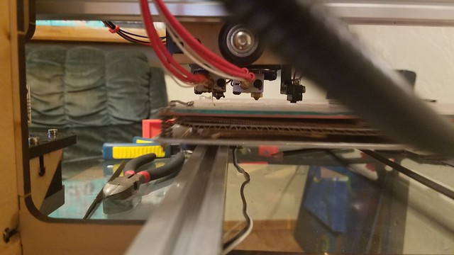
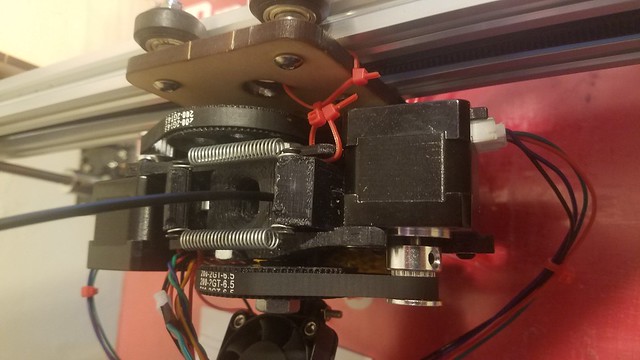
Here are a couple photos of the 50 mm offset and a small mod I did to help keep the x-carriage from sagging.
-
07-08-2017, 07:06 PM #30Student

- Join Date
- Jul 2016
- Posts
- 43
About to do the G26 steps:
Starting with this map
Bed Topography Report:
(0,9) (9,9)
(11,309) (309,309)
0.040 0.040 0.040 0.073 0.090 0.092 0.110 0.083 0.070 0.070
0.012 0.012 0.012 0.033 0.060 0.058 0.055 0.028 -0.005 -0.005
-0.015 -0.015 -0.015 -0.007 0.030 0.023 0.000 -0.027 -0.080 -0.080
-0.022 -0.022 -0.022 0.005 0.017 0.002 -0.015 -0.080 -0.120 -0.120
-0.010 -0.010 -0.010 [ 0.012] 0.023 0.000 -0.017 -0.077 -0.150 -0.150
-0.010 -0.010 -0.010 0.020 0.028 0.002 -0.027 -0.090 -0.150 -0.150
-0.005 -0.005 -0.005 0.025 0.033 0.005 -0.022 -0.095 -0.155 -0.155
0.007 0.007 0.007 0.023 0.028 0.010 -0.027 -0.092 -0.140 -0.140
0.025 0.025 0.025 0.028 0.033 0.010 0.002 -0.077 -0.115 -0.115
0.030 0.030 0.030 0.050 0.063 0.055 0.043 -0.010 -0.017 -0.017
(11,1) (309,1)
(0,0) (9,0)
 20170708_174916 by plackslayer79, on Flickr
 20170708_174823 by plackslayer79, on Flickr
 20170708_174811 by plackslayer79, on Flickr
 20170704_121719 by plackslayer79, on Flickr


 Reply With Quote


Ender 3v2 poor printing quality
10-28-2024, 09:08 AM in Tips, Tricks and Tech Help