


Results 1 to 10 of 255
Hybrid View


-
08-13-2014, 10:53 AM #1Student

- Join Date
- Aug 2014
- Posts
- 25
is there in cura settings for the 10" i3v that i can jut load in?
-
08-13-2014, 12:33 PM #2Staff Engineer
- Join Date
- May 2014
- Location
- Highlands Ranch, Colorado USA
- Posts
- 1,437

No, but I wouldn't let that scare you away from trying Cura. IIRC, there's only four areas where settings are made. File | Machine Settings is where you'd set the size of your print area, type of G-code (set it to RepRap), etc. The Basic tab is where parameters are adjusted for almost every print - temperatures, print speed, etc. The Advanced tab has more settings that you'll likely only adjust once-in-awhile, such as first layer details. Settings under Expert | Expert Config allow you to tailor the support structure, raft, brim, etc. for when those options are enabled on the Basic tab. Originally Posted by nefiwashere

Other than Machine Settings, the only thing I remember really feeling the need to initially tweak was the retraction speed and distance under Advanced. Mine is set to 10mm/sec speed and 1.0mm distance. As clough42 has educated us, the MakerFarm extruder motor works better with a slower retraction speed, and we don't have a Bowden setup so the default of 4.5mm retraction distance is excessive for us.
Ultimaker has an on-line manual for Cura that walks through what you need to do for your "first print" with it. That'd be a good place to start. The manual is focused on those with an Ultimaker printer, but they do have info on how to use Cura with non-Ultimaker printers.
-
09-12-2014, 01:49 PM #3Staff Engineer
- Join Date
- May 2014
- Location
- Highlands Ranch, Colorado USA
- Posts
- 1,437
EXTRUDER REBUILD AND NEW PRINT COOLER (Part 2 of 2)
PRINT COOLER
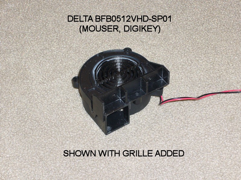
FOLLOWUP COMMENT: According to an end-of-life notice from DigiKey, the manufacturer has transitioned the specific fan suggested here to obsolete status. I believe Mouser has already dropped it from their catalogue. DigiKey still had stock the last time I checked. It may not be available for future readers of the thread. Unfortunately, the fan was used because of its very unique mounting provisions, and I am not aware of a suitable substitute.
Since putting a focusing shroud on an axial fan creates backpressure that usually reduces fan airflow, this time I wanted to use a radial blower for the print cooler. After considering several concepts, I opted to go with a Delta BFB0512VHD-SP01 blower mounted onto the left side of the X-carriage. I added a grille to the blower intake by aborting a print of http://www.thingiverse.com/thing:401935 as the ring part was done, trimming off the part of the rings that didn't fit into the opening of the blower.
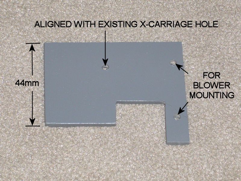
I fastened the blower to a 64-mm by 54-mm piece of 1/8-inch hobby plywood that attaches to the existing X-carriage, replacing the original bolt on the left side of the carriage with a longer one. This specific blower is unique in that it has mounting provisions on the face with the blower opening, providing a straight shot from the blower to the print. One advantage of having the blower on the separate bracket is that the connectorized print cooler assembly can be easily added to or removed from the printer.
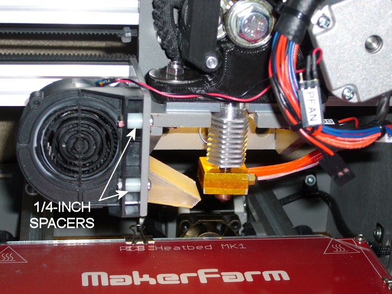
The blower is located forward enough so that the blower outlet clears the angled sidewall of the X-carriage, and located just high enough to provide binder clip clearance above the print bed glass. A simple duct inserted into the outlet of the blower helps keep airflow off the hot end. The adapted version of the final duct I'm using is http://www.thingiverse.com/thing:461014. The duct is just press fit to provide some adjustment to the airflow angle, and to allow the duct to be swapped out without a lot of fuss.
Especially combined with a straight-shot duct (no right angles or rotational vortex to worry about), this is a very effective blower. Cooling is very adequate with the fan only running in the 10% range. At that speed, the audible whine from the low frequency Marlin uses on the fan PWM overpowered the low blower noise. This was resolved by a minor firmware change to have Marlin use the higher frequency fan PWM (see MINOR FIRMWARE PERSONALIZATION). The airflow is also focused and linear. At 100% blower speed, air from the blower can be felt several feet from the printer.
Note that the blower used is a 4-wire type. The red and black wires are wired to RAMPS D9. The other two wires aren't used. I cut them off and insulated the cut ends with small heatshrink tubing.
FOLLOWUP COMMENT: On large, straightforward prints where cooling won't be an issue, I've been running the blower at 10%. On more complex prints, I'll let Cura set the print speed between 10% and 25%. On really complex things, I'm finding it best to not have Cura control the fan speed and I'll do it manually through Repetier-Host. That way I can increase the speed to as much as 100% if I sense the need to for a bit, or I can back it down if I see the blower dropping the hot end temperature too much. When cooling is enabled in the slicing, Cura apparently sets the fan speed on every layer, so trying to manually override the temperature with Repetier-Host only works for the balance of that layer before the fan speed is set again in the gcode.Last edited by printbus; 04-22-2016 at 07:37 AM. Reason: fan is obsolete
-
10-01-2014, 07:50 PM #4Staff Engineer
- Join Date
- May 2014
- Location
- Highlands Ranch, Colorado USA
- Posts
- 1,437
Also, let's not panic here. I think I'm the first raising the possible theoretical issue of running an ABL servo on a standalone printer, and I don't even have ABL implemented. We need feedback from people with ABL experience on whether they've seen ABL (or the entire Arduino electronics suite) ever acting up when standalone.
The symptom of the MEGA2560 voltage regulator going into thermal protection is that the 5V gets shut off until the regulator cools off, and then the regulator will turn back on. That should be a pretty noticeable symptom, and I don't recall hearing anyone describing their printer going dead momentarily.Last edited by printbus; 10-01-2014 at 08:11 PM.
-
10-07-2014, 12:11 PM #5Staff Engineer
- Join Date
- May 2014
- Location
- Highlands Ranch, Colorado USA
- Posts
- 1,437
Wait. On the extruder? Are you talking about the long screws used with the guidler plate that pivots? They're longer than 25mm and I believe can be hard to find. Just not sure where else there's an M3 with a nut on it.
-
10-08-2014, 09:17 AM #6Staff Engineer
- Join Date
- May 2014
- Location
- Highlands Ranch, Colorado USA
- Posts
- 1,437
Once you have the clips on just the glass and the heat bed, you may find like I did that the clips are actually pretty large. In the HEAT BED CLIPS post, I show how much better the next smaller size of clip fits. They barely encroach on the print area marking on the heat bed, and wouldn't conflict with the cork or any other insulation as much.
Last edited by printbus; 10-08-2014 at 09:20 AM. Reason: grammar
-
10-08-2014, 09:43 AM #7Technologist
- Join Date
- Aug 2014
- Location
- Oklahoma
- Posts
- 191

 I haven't seen that post, so I will go check it out thanks printbus and gmay3 also! Originally Posted by printbus
-
09-12-2014, 01:25 PM #8Staff Engineer
- Join Date
- May 2014
- Location
- Highlands Ranch, Colorado USA
- Posts
- 1,437
EXTRUDER REBUILD AND NEW PRINT COOLER (Part 1 of 2)
An unplanned softening of the extruder base gave me the opportunity to rebuild the extruder, rethinking some of it during the process.
EXTRUDER PRINTED PARTS
I had previously printed my replacement parts at 75% infill. That should provide a solid base that holds up to the stress of the motor bolts and the extruder mounting bolts. I also use fender washers and nylon locknuts on the extruder mounting bolts instead of the nut captures in the base.
For infill comparison, the base MakerFarm provided was likely printed at 25% infill based on Cura slicer weight estimates.
The shaft hole in the small extruder gear was presized with a 5mm drill bit. To ensure a true hole, a drill press was used.
EXTRUDER MOTOR
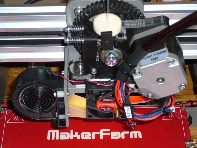
My i3v kit included CW type 42BHH48-050-24A stepper motors that generally run hot. In the rebuild, the extruder motor was replaced with a Kysan 1124090. Compared to the CW, it's nice having an extruder motor that doesn't even get warm. No more shroud or cooling fan on this motor. As a side benefit, I noticed the Kysan uses 22 AWG wiring. The CW motor was only 26 AWG. Less voltage drop in the motor wiring should maximize the power being applied to the Kysan motor.
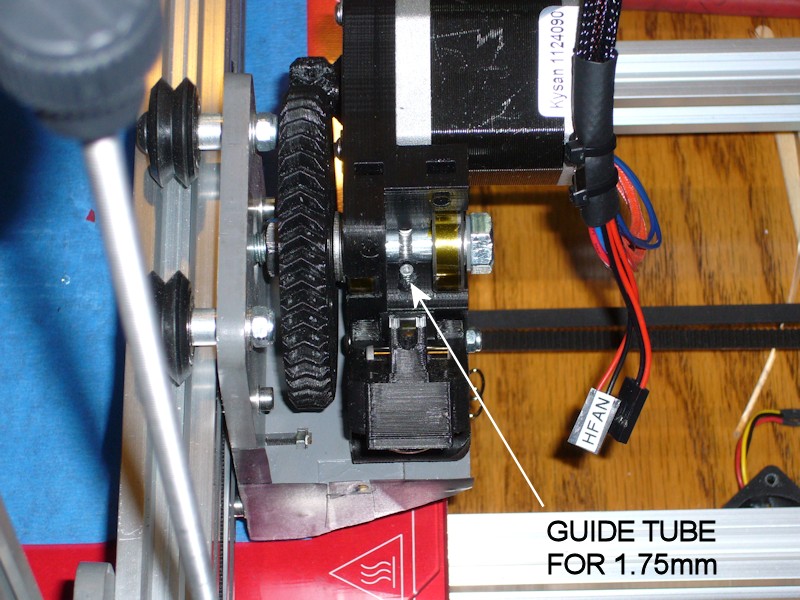
FILAMENT ALIGNMENT TUBE
It seems like luck has always been required to successfully feed 1.75mm filament into the body of the hexagon hot end, likely because the feed hole at the bottom of the extruder base is large enough to also accommodate 3mm filament. I'd often have to use a flashlight and futz around with aligning the filament with the top of the deeply recessed hot end. To ease this, I've added a 25-mm length of 3mm OD aluminum tube to the extruder base feed hole below the hobbed bolt. The tubing I used (K&S 9802 from a hobby store) has 0.45mm wall thickness, so the tubing ID should be more than adequate to handle any normal 1.75mm tolerances that still fit the hot end. A small amount of flexible adhesive was used to ensure the tube remains in place during retractions and when swapping out filament. To feed filament, now I only need to get it into the top of the alignment tube, and the end of the aluminum tube is visible from above without using a flashlight.
FOLLOWUP COMMENT: I probably rate the filament guide tube mod as the second slickest mod I've incorporated into my printer, right behind the screw-adjustable Z-endstop approach. It is so much easier to feed filament now.
FOLLOWUP COMMENT #2: I don't remember who it was, but someone mentioned in another thread that a portion of an empty ink tube from a BIC-type pen also works as the alignment tube for 1.75mm filament.
HOBBED BOLT
I used a thin nylon washer combined with several thin 8-mm ID shims under the head of the hobbed bolt as required to optimize alignment of the cut in the hobbed bolt with the filament channel in the extruder assembly. The shims I used were from a Calandra Racing Concepts axle shim kit #4738.
Many people use the Gregg's Accessible Extruder without issues, but I just don't get part of the mechanical design. To improve the fit and minimize radial play of the hobbed bolt in the bearings, I wrap the bearing areas of the hobbed bolt with some kapton tape. Seems like a good thing, right? The problem is that the inner races of the hobbed bolt bearings rub against the plastic of the extruder base. Leave the hobbed bolt too loose and you might have axial play in the bolt. Too tight and the inner bearing races will bind on the extruder base, and if the hobbed bolt isn't loose in the bearings (like if the bolt is wrapped with tape so it is snug in the bearings), there'll be drag on the hobbed bolt rotation. Does the Greg's design assume the hobbed bolt will just spin inside the inner bearing race? If so, why were bearings even used? I don't see an easy solution here, but the base design could at least have a bit of a recess to provide clearance for the inner races of the bearings.
FOLLOWUP COMMENT: I believe the original design may have intended for large-id washers to be be used between the base and the bearings. Spacer rings are included in some Thingiverse versions of the Greg's Wades extruder such as this one - http://www.thingiverse.com/thing:18379.
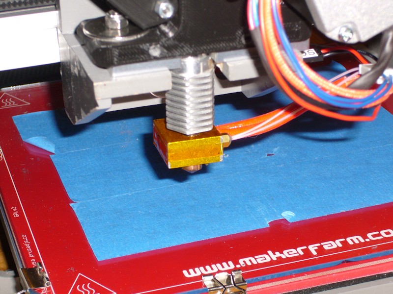
HEXAGON HOT END ASSEMBLY
I thought I had previously misthreaded the aluminum block on my hex hot end, so I bought a 20-mm block and 20-mm heater to use in the rebuild. During reassembly, I essentially applied part of Tom's E3D v6 assembly instructions, in that the tip is NOT tightened up against the aluminum block. A benefit of this on the hex hot end is the hex heatsink can be oriented how you want it, and the tip is then tightened up against the barrel of the heat break. I also wrapped the aluminum block in kapton to provide some insulation from airflow caused by the heatsink cooling fan and from the print cooler. I don't like the idea of a thick insulator on the top of the block since it could restrict airflow below the important lowest fin on the heatsink. Multiple layers of kapton were also added to the flat top end of the hot end to ensure a snug fit when the extruder is bolted onto the carriage. These layers were trimmed to clear the filament feed hole.
FOLLOWUP COMMENT: The tip was retightened when it was brought up to temperature the first time.
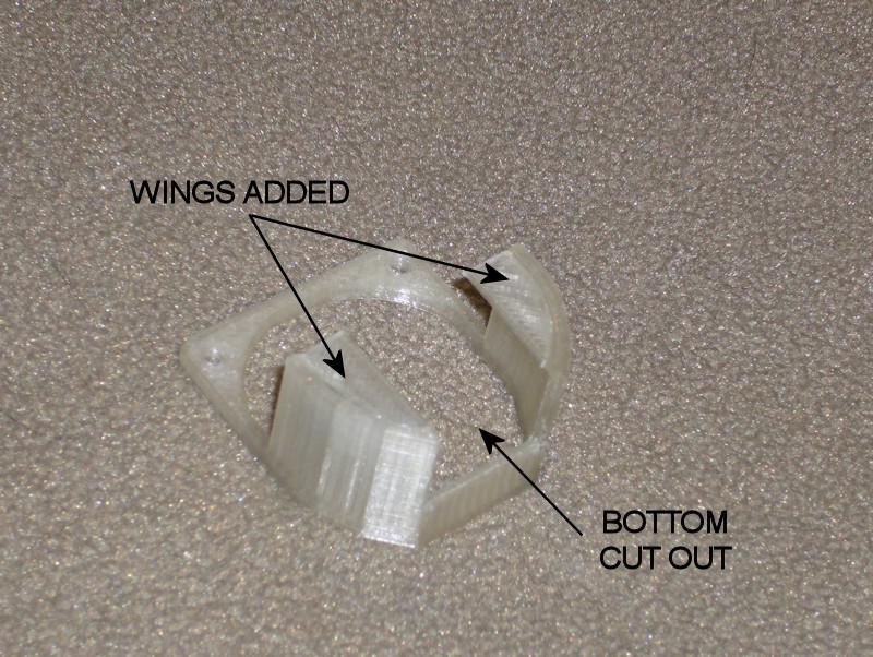
HEXAGON HOT END COOLING SHROUD
In previous mods, I've already been cutting out the flat part of the shroud that sits above the aluminum block of the hexagon hot end, since it'll likely melt away anyway. In the rebuild, I also added some "wings" to the rear of the shroud to help ensure airflow is forced onto the hot end heatsink rather than just bypassing around it. I cut the wings from some thin printed PLA sheet and attached them using medium-CA.
FOLLOWUP COMMENT: I later migrated to a custom design for the shroud discussed in post New Approach for the Hexagon Hot End Shroud.
FOLLOWUP COMMENT: Since I mention it in another thread, I'll add that there was another problem I was trying to solve in the extruder rebuild. Since resolving or minimizing noise sources earlier, I was left with an annoying creak somewhere in the extruder. Using a hose as a listening tube, it seemed like the noise was coming from the area of the hobbed bolt or the filament idler. I actually had the extruder apart multiple times to try to eliminate it. I ultimately applied everything I could think of in a final build, including the use of new bearings on the hobbed bolt, new kapton tape on the hobbed bolt, lubricating where the bearing inner races can ride on the plastic of the extruder base, etc. Somewhere in the final attempt when the new motor was also installed the creak has in fact been eliminated.Last edited by printbus; 05-03-2015 at 10:51 AM. Reason: migrated to offsite image storage due to 3DPrintBoard issues

 Reply With Quote


Please explain to me how to...
05-17-2024, 12:15 PM in 3D Printer Parts, Filament & Materials