


Results 1 to 10 of 255
Hybrid View


-
05-31-2014, 03:14 PM #1Staff Engineer

- Join Date
- May 2014
- Location
- Highlands Ranch, Colorado USA
- Posts
- 1,437

ENDSTOP INSTALLATION
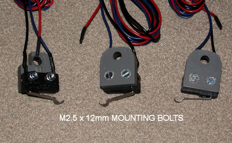
To provide a more permanent endstop setting, I wanted to use bolts and nuts to attach the switches to the endstop brackets instead of zip ties. Holes in the switches are sized for M2.5 hardware. So that the bolt heads wouldn't interfere with the aluminum rails on the back side of the brackets, I used a 3/16-inch drill bit to countersink the M2.5 screw heads. This allows the brackets to mount flush to the rails - another advantage over the zip ties. M2.5 x 12mm screws worked well for mounting the switches. As a good practice, heatshrink was used on the wire connections at the switches. For now, I left the unused red wire in the end stop cables. I assume the RAMPS board puts something like 5V on that wire, which isn't needed in the i3v. Since I plan to sleeve wire bundles wherever I can, I wanted to retain this for future use should I want to upgrade to optical sensors, add lights, etc. Heatshrink was added to cover the ends of the red wire and the wire will be folded over inside the sleeving when I get that far.
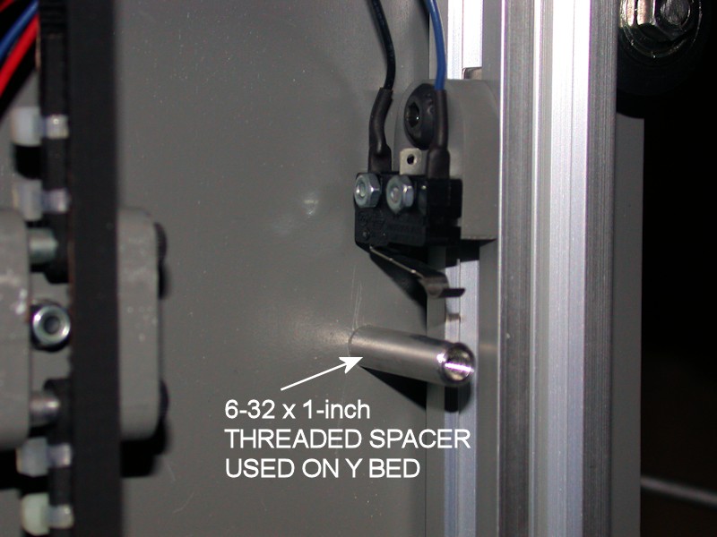
To improve how the Y bed hits the Y endstop switch, the M3 bolt on the Y bed was replaced with a 6-32 bolt and threaded aluminum spacer 1-inch long.
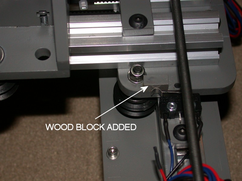
Since I was already weakening the Z-stop bracket slightly by countersinking the bolt heads, I didn't want to shave material off the back side of the mounting bracket as done in the build video. Instead, I glued a small piece of wood scrap from the kit's plywood sheets to the X idler. This gives a good surface area for the Z endstop switch to hit - it's probably a better fix than shaving off the back of the endstop plate anyway. At some point, I may decide to add a similar wood piece to the X carriage for the X end stop.
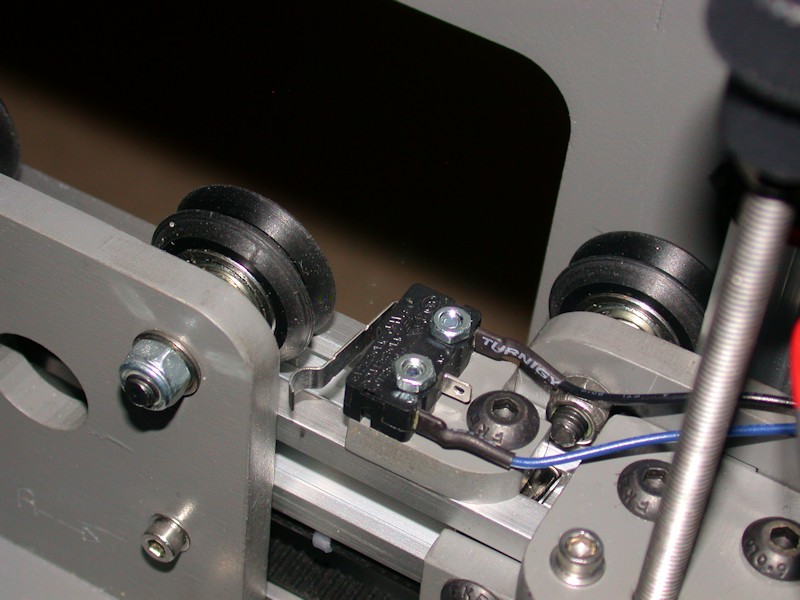
NOTE: Switch locations in the photos are not final. They'll be adjusted later.
FOLLOWUP COMMENT #1: The unused red wires got pulled out of the connectors for the endstop switches fairly quick. They were just getting in the way.
FOLLOWUP COMMENT #2: In the later WIRE ROUTING (PART 2) post, I relocate the X endstop switch to the bottom of the lower aluminum rail. This requires the switch to mounted on the reverse side of the switch bracket from what is shown in the picture. I also later increased the length of the notch in the switch bracket so that it could slide farther past the nut on the wheel bolt. The small wood block added to the X idler extends farther towards the wheel bolt than it needed to. I got very lucky here. When I moved the X endstop switch to the bottom of the lower extrusion, that small block almost got in the way. I should have kept it shorter.
FOLLOWUP COMMENT #3: Clough42 has several upgrades for the i3v available on Thingiverse, including endstop switch brackets designed to fit the V-groove of the aluminum rail. I found the MakerFarm approach for the Z endstop especially lacking. Clough42 has a great improvement that provides a screw-based Z endstop adjustment. This eliminates the reason for adding the small wood block or shaving off the back of the Z endstop bracket.
FOLLOWUP COMMENT #4: Those clough42 switch brackets only work with the 8-inch printer. There's a similar solution for the 10-inch printer from another user on Thingiverse.Last edited by printbus; 05-03-2015 at 12:14 AM. Reason: migrated to offsite image storage due to 3DPrintBoard issues


 Reply With Quote


Please explain to me how to...
Today, 02:43 PM in 3D Printer Parts, Filament & Materials