


Results 1 to 10 of 255
Hybrid View


-
05-30-2014, 01:31 AM #1Staff Engineer

- Join Date
- May 2014
- Location
- Highlands Ranch, Colorado USA
- Posts
- 1,437

Y Motor subassembly
Y MOTOR SUBASSEMBLY
I oriented the motor so that the wires come out of the motor towards the rear. Since I plan to really work cable routing appearance, this should provide the cleanest routing option.
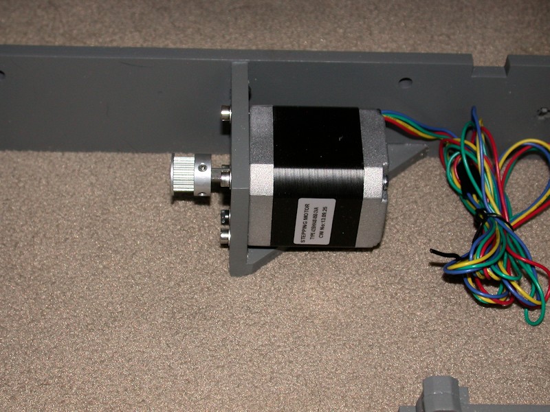
I didn't like the way the set screws provided in the kit ended up being recessed in the pulley threads, so I obtained some M3 x 6mm set screws to use instead. Note that the pulley isn't in the final position on the motor shaft in this picture. M3 flat washers were added to the motor mounting bolts. This takes away from thread engagement in the motor, so I swapped out the 10mm long bolts for 12mm long ones. These are close to bottoming out in the motors, so they're providing as much thread engagement as possible.
FOLLOWUP COMMENT: The natural way to install the motor is to set the motor in the bracket and bolt it in place. I believe one of the sources of vibration I had in the i3v is the bottom side of the Y-motor rattling on the bottom of the motor bracket during certain print moves. I later added some thin silicone sheet material there that helped. Even adding a few layers of high temperature electrical tape might help provide some cushion. The material needs to be very thin or the motor bolt holes won't line up with the holes in the bracket.
FOLLOWUP COMMENT #2: When I later replaced the original CW motors with Kysan motors, the 12 mm screws were too long and I reverted back to 10mm. When the motors were replaced, I added a layer of fiberglass tape to the mounting face of each motor, mainly to keep the motor faces from sticking to the painted surfaces but also to provide at least some vibration isolation.Last edited by printbus; 05-02-2015 at 11:51 PM. Reason: migrated to offsite image storage due to 3DPrintBoard issues
-
06-01-2014, 02:45 AM #2Staff Engineer
- Join Date
- Oct 2013
- Location
- Narellan, New South Wales, Australia
- Posts
- 912
Every time I look at this build thread, I am impressed by the appearance of the printer. It really is competitive with those unbox, plug in, print ones in aesthetic appeal. If it prints like the original i3 it's a real winner.
OME
-
06-01-2014, 09:00 AM #3Staff Engineer
- Join Date
- May 2014
- Location
- Highlands Ranch, Colorado USA
- Posts
- 1,437
Thanks, OME! You're grasping where I'm trying to head with this build. Yeah I've ran into a few minor things, but I'm still pretty happy with the i3v design - I see no reason why it shouldn't be a great printer. I'm futzing around with the build more than I thought I would, but I'm in no hurry. The way I study things tends to drive people around me nuts. I think the kids are glad that they're old enough to have moved away from it. And in this case, the wife has long ago stopped asking if I'm ready to print yet. Originally Posted by old man emu

-
06-01-2014, 07:08 PM #4Staff Engineer
- Join Date
- Oct 2013
- Location
- Narellan, New South Wales, Australia
- Posts
- 912
Oh! She's completed Phase One of her campaign. Phase Two is when she starts asking why you have to keep spending money on that damned printer. "I thought you said it had everything in it that you needed!" Originally Posted by printbus
OME
-
06-01-2014, 07:34 PM #5Staff Engineer
- Join Date
- May 2014
- Location
- Highlands Ranch, Colorado USA
- Posts
- 1,437
Ha! Yeah, the "didn't it come with what you needed" has already came up. She knows me, though, and all I had to do was say I found a way to improve it and needed to make a run to the local Ace Hardware. To that her response has been "oh, so you're not done Kevinizing it yet". So far, working on the printer has been nothing like the ongoing investment I've had with RC helicopter repairs, but I can see the similarities the future may bring. Originally Posted by old man emu
No build progress today - too much time spent living life.Last edited by printbus; 06-05-2014 at 04:20 PM.
-
06-03-2014, 06:22 AM #6Staff Engineer
- Join Date
- Oct 2013
- Location
- Narellan, New South Wales, Australia
- Posts
- 912
LED Illumination
Here are some pix to show how my 3 x LED light strips illuminate the print area.
Here is the print area with the lights off:
Lights Off.jpg
and with the lights on (no flash for photo)
Lights On.JPG
Here's how it looks in photos taken with a flash.
Lights off
Lights Off - flashlit.jpg
Lights on
Lights On - flashlit.jpg
Here's the link to how I did it: http://3dprintboard.com/showthread.p...the-Print-Area
Old Man EmuLast edited by old man emu; 06-03-2014 at 07:13 PM.
-
06-03-2014, 07:23 AM #7Super Moderator
- Join Date
- Apr 2014
- Location
- Lone Star State
- Posts
- 2,182
I have a couple of LED's embedded into my extruder to do the same thing. But they burned out. They still light up but are not bright enough to serve any purpose now. I like the light strip idea. I think I'll go scrounge on eBay and see if I can find something suitable for my setup!
-
06-06-2014, 10:05 AM #8Staff Engineer
- Join Date
- May 2014
- Location
- Highlands Ranch, Colorado USA
- Posts
- 1,437
MOTOR TESTING AND ENDSTOP ADJUSTMENT
It was great to finally be controlling the motors from the LCD. In my case, I had to reverse the plugs for both the X motor and the Y motor at the RAMPS board to get the proper movement directions. No issues surfaced in adjusting a general placement of the Z endstop switch.
Some may recall I put two zip ties on each of the belt ends. On the leg of the Y belt that loops forward through the Y idler, I had to move the forward zip tie closer to the belt mounting bolt, since it was tending to catch on one of the idler pulley brackets when the bed was fully extended. I also trimmed off some of the excess belt so it wouldn't encroach on the idler bearings. After that, I could position the Y endstop switch so the home position of the hot end is at the rear marking of the square on the heat bed.
Adjustment of the X home position wasn't as easy. With the endstop switch as far right as it would go, the hot end tip was still about 6mm inside the marking on the heat bed. I can't imagine ever printing anything that actually needs the full 200mm capability, but I took on achieving it as a challenge. Several tweaks were involved, with each providing just a portion of the correction.
- Using a round needle file, I elongated the extruder mounting holes in the X carriage to allow the extruder to slide to the right maybe 1.5 or 2mm. For good measure, I enlarged the large U-shaped channel for the hot end an equal amount. I probably could have elongated the holes a bit more, but at some point the head of the right-side extruder mounting bolt will be up against the carriage sidewall and limit how far the extruder can slide over.
- Having previously relocated the X endstop switch to the bottom X axis aluminum rail turned out to helpful. On the upper location, the range of adjustment of the X endstop switch is limited by the Z nut bracket on the X idler. The bottom side doesn't have that problem. I cut out 1.5 or 2mm of additional wood from the notch in the X endstop bracket so it could pass farther over the nut for the lower X idler wheel bolt.
- Although the notch clears the locknut, now the wide button head screw mounting the X endstop was binding up on the bolt protruding from the wheel bolt locknut. Shortening the bolt would have required some serious disassembly, so I swapped the button head on the endstop bracket with a normal cap screw which has a slightly narrower head.
- Using a needlenose pliers, I "flattened" most of the U-hook out of the endstop switch lever so the X carriage travels farther before the switch activates.
- Finally, I angled the endstop bracket on the extrusion just a bit to rotate the end of the switch lever away from the X carriage.
I wanted to measure and record the baseline current limit settings for the stepper motor drivers. That led me to realize the trimpot on the Z driver was broken and the entire top half with the wiper was gone. I appeared to be driving the motors OK, but I'm not sure how the A4988 chip deals with the now unconnected current limit input signal. I'm limiting what I do with the printer until I get the replacement driver. The top part of the trimpot was later found in the bubble package from the RAMPS board.
FOLLOWUP COMMENT: The Pololu Black stepper driver I purchased got here before the MakerFarm replacement, so I've installed the Pololu.Last edited by printbus; 08-10-2014 at 11:50 PM.
-
06-03-2014, 03:26 AM #9Staff Engineer
- Join Date
- Oct 2013
- Location
- Narellan, New South Wales, Australia
- Posts
- 912
Just a suggestion:
Rotate your RAMPS board 180 degrees. That will give you easier access to the endstop, thermistor and extruder stepper connections. It will also make it easier to access the power and heater (both) connections. It does put the flat cable to the LCD in the way, but that is a small price to pay for better access. I actually attached a plywood plate to the top frame member and have my RAMPS board on top of the printer, to the left of the LCD screen. Really easy access.
Here's how mine looks:
Relocated RAMPS board.jpg
Old Man EmuLast edited by old man emu; 06-03-2014 at 05:47 AM.
-
06-03-2014, 12:53 AM #10Staff Engineer
- Join Date
- May 2014
- Location
- Highlands Ranch, Colorado USA
- Posts
- 1,437
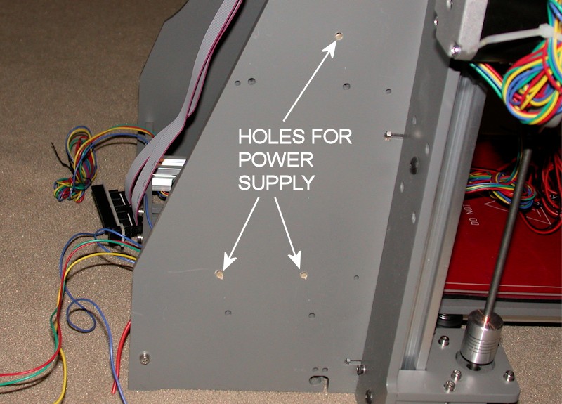
POWER SUPPLY AND RAMPS MOUNTING
I ended up not using the holes MakerFarm provides on the left sidewall for a Mean Well type power supply. I moved the power supply rearward a bit to open up the airflow slots on the forward edge of the power supply, and I moved the power supply upward in order to provide more wiring access room at the power supply terminal block. This does mean, however, that the power supply is now only mounted at three points.
I also used #8 x 1/4-inch aluminum spacers on the power supply in order to open up the airflow slots on the mounting side of the power supply. I'd rather the power supply fan run as little as possible, and I'm hoping these changes improve the cooling obtained just by convection.
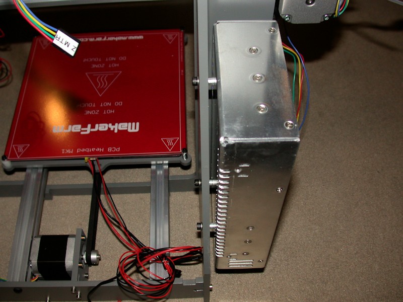
The RAMPS and heater relay were mounted in the provided holes. I threw spacers on these too, mainly so I could tuck wires under the boards.
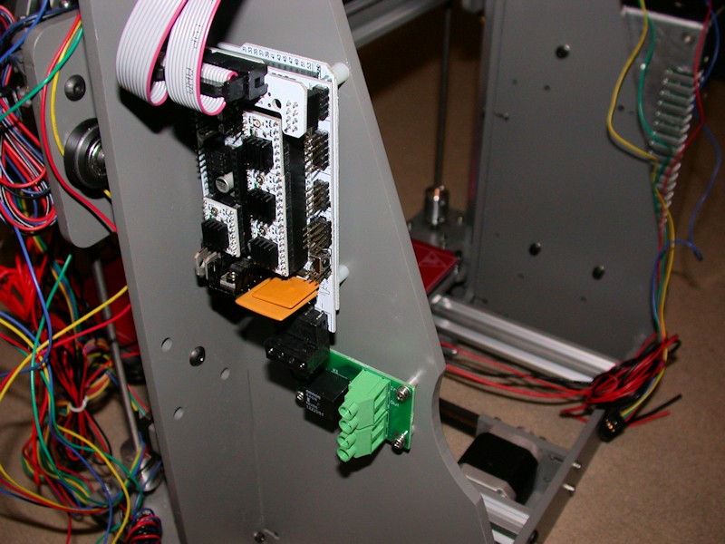
FOLLOWUP COMMENT #1: One of my tougher vibrations to track down turned out to be on the RAMPS board. The two large yellow square components (polyfuses) were touching, and at certain print speeds they'd rattle. To fix that, I added a dab of hot glue between them to ensure the two components aren't touching.
FOLLOWUP COMMENT #2: If you're downloading the Marlin firmware at this point in your build, DO NOT follow the instructions in the build guide RAMPS firmware video on where to get it. I learned the hard way that will get you the firmware intended for the i3, not the i3v. There are some subtle differences in the firmware configuration files. Obtain the files from the RAMPS download link provided in the i3v build guide.Last edited by printbus; 05-03-2015 at 07:03 AM. Reason: migrated to offsite image storage due to 3DPrintBoard issues


 Reply With Quote


Please explain to me how to...
05-17-2024, 12:15 PM in 3D Printer Parts, Filament & Materials