


Results 1 to 10 of 255
Hybrid View


-
08-13-2014, 07:39 PM #1Engineer

- Join Date
- Jul 2014
- Location
- Eastern Colorado
- Posts
- 536
Thanks. I think I may emulate that setup, with two header sockets, though. I currently have two switches on my printer, one for fans and one for lights, and this header socket idea will make connecting fans and lights easier, as well as leaving an open, easily-accessible place to add more if needed, as you said.
-
08-13-2014, 08:12 PM #2Staff Engineer
- Join Date
- May 2014
- Location
- Highlands Ranch, Colorado USA
- Posts
- 1,437

Sounds like a plan. Another thing I liked about the header approach is that any extra, unused connections were well protected. No exposed screws on a terminal board, etc. Originally Posted by AbuMaia

Last edited by printbus; 09-22-2014 at 01:39 AM.
-
09-22-2014, 01:10 PM #3Staff Engineer
- Join Date
- May 2014
- Location
- Highlands Ranch, Colorado USA
- Posts
- 1,437
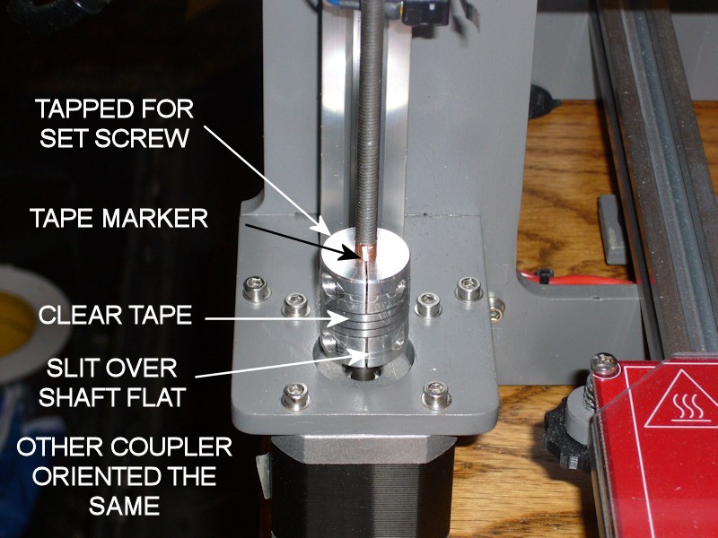
TWEAKS TO THE COUPLERS ON THE Z-AXIS RODS
During bed leveling after the recent extruder rebuild, I noticed one of the threaded rods was slipping inside the spiral shaft coupler. Things have been printing fine, and I'm not sure how long this has been loose. Things were likely printing fine because of the way I had aligned the X-axis as part of the original build.
When I built the printer, I had already purchased the "split collar" type of couplers before I learned there is another type that uses two pairs of set screws to grab the shafts. Now I wish I had purchased the set screw type instead. Sticking with what I had, I made some improvements.
- I tapped both couplers for an M3 x 6mm set screw as a secondary grip on the shafts.
- I made sure the two couplers were oriented the same way. I hadn't done this before, and one coupler was inadvertently upside down from the other. They'll work fine either way, but having them oriented the same way makes it easier to tell at a glance whether one is unintentionally rotated off from the other.
- This time I think I put more attention to how the clamping end is oriented over the flat of the motor shafts. Now the open slit is right above the flat; tightening the clamping screw should provide the most grip on the motor shaft.
- Before tightening the threaded rods in the couplers, I made sure the two motors shafts were rotated so the shaft flats (and couplers) are rotated to the same position. Again, this will just make it easier to see if one motor is off from the other.
- After rechecking alignment between the X-motor and X-idler plates and tightening the couplers onto the threaded rods, I added narrow slivers of tape onto the threaded rods. The slivers of tape are placed in line with one of the cuts in the coupler ends to also serve as a quick-glance indicator that the rods are slipping in the coupler. I left enough of the foil tape wrapped around the threaded rods to stick the tape sliver to, although this would mean I wouldn't notice the threaded rod slipping inside the tape.
- I've had a high frequency whine often present when lowering the X-carriage down to the print bed. This was found to be coming from the spiral winding of the shaft couplers. I added two turns of clear tape over the spiral part of the couplers to provide a dampening effect that has eliminated the whine.
Last edited by printbus; 05-03-2015 at 03:25 PM. Reason: migrated to offsite image storage due to 3DPrintBoard issues
-
09-30-2014, 09:44 PM #4Engineer-in-Training
- Join Date
- Jul 2014
- Posts
- 204
Kevin - I tried the usb 5V isolation thing and got erratic operation of my ABL servo. the failure went away after removing the kapton from the connector. Does it make sense that removing that source of 5V might interfere with somethign in the RC servo section of the board?
-
10-01-2014, 07:44 AM #5Staff Engineer
- Join Date
- May 2014
- Location
- Highlands Ranch, Colorado USA
- Posts
- 1,437
Interesting. It could be that there IS a connection. Here's my theory - Originally Posted by TopJimmyCooks
5V power for the MEGA2560 board, RAMPS (mainly any servos connected to it) and the LCD panel can normally come from either the USB port or a fixed voltage linear regulator on the MEGA2560 board. With no 5v in the USB cable, 5v power will have to come from the fixed regulator on the MEGA2560 board. To provide maximum torque throughout the desired movement, RC servos typically operate through application of a series of short pulses of power to the servo motor. Each one of these pulses is going to draw a surge of current from the regulator, with the amount of surge dependent on the actual servo being used and the amount of mechanical load on the servo. It could be that these surges are more than the fixed regulator can handle. The other possibility is that there's a power dissipation issue with the voltage regulator supplying 5V for the servo(s) connected to the RAMPS board. Either could cause dropouts in the 5V output that could lead to erratic operation of the MEGA2560, the servos, or the LCD panel.
It could be that there are multiple factors involved. For example, perhaps there's only a small drop in the regulator voltage, but that is combined with voltage drop in the lengthy wiring required to get 5V to the ABL servo.
I'm not sure having a servo that moves too far as mentioned in your original thread would be a symptom I would expect, but who knows. I'll add a cautionary note regarding ABL to the post suggesting the USB cable mod.
FOLLOWUP COMMENT: The Power Supply section of http://reprap.org/wiki/RAMPS_1.4 does imply that there are concerns powering servos from the Arduino (MEGA2560) unless you're running the Arduino directly from a 5V supply or USB power. This would mean you have to also be wary about using a printer with ABL standalone, when no computer is connected to provide the additional 5V power needed for the ABL servo:"The 5V pin in that connector on RAMPS only supplies the 5V to the auxiliary servo connectors. It is designed so that you can jumper it to the VCC pin and use the Arduino's power supply to supply 5V for extra servos if you are only powered from USB or 5V. Since there is not a lot of extra power from the Arduino's power supply you can connect it directly to your 5V power supply if you have one."FOLLOWUP COMMENT #2: For the technically curious... The vague "...not a lot of extra power from the Arduino's power supply" statement in the wiki caused me to look at that some more. Per the Arduino baseline, the fixed regulator on the MEGA2560 is an ON Semi NCP1117ST50T3 part. Calculating the maximum power dissipation allowed in a linear regulator is always tricky, since you're having to estimate the design's ability to dissipate heat away from the part. For the SOT-223 regulator package being used here, the datasheet does have Figure 21 that shows how much power dissipation is acceptable for a given square of 2-ounce copper plane around the part. The graph tops out at just over 1.4 watts; let's take that as a maximum amount of power we would want to see in the printer application even though the copper on the board isn't exactly a square, we don't know the copper thickness, the RAMPS board is going to limit airflow, etc. With the printer not doing anything, I measure 140mA of 12V current going into the MEGA2560 board, and this should equate to the current flowing through the 5V regulator. So, without an ABL servo the power dissipation in the 5V regulator is already just about a watt. The math is P=V*I or (12-5)*0.14=0.98 watts. This is already well into our maximum. Using our notional 1.4W limit on the power dissipation, the maximum amount of current we could draw is I=P/V, or 1.4/(12-5)= 0.2 amps. This is only 60 mA above what I've already measured. Whatever margin the MEGA2560 board had in 5V regulator capacity is likely considered used up by the LCD smartpanel. This again emphasizes that those with an ABL servo may not want to operate the printer, or at least may not want to do a lot of bed leveling servo movement, without power being applied by USB or they risk overheating the 5V regulator. The saving grace is that bed leveling isn't a forever thing. The trick would be to get extra load from moving the ABL servo over quick enough.
Last edited by printbus; 10-01-2014 at 08:12 PM.
-
09-14-2014, 05:09 PM #6Staff Engineer
- Join Date
- May 2014
- Location
- Highlands Ranch, Colorado USA
- Posts
- 1,437
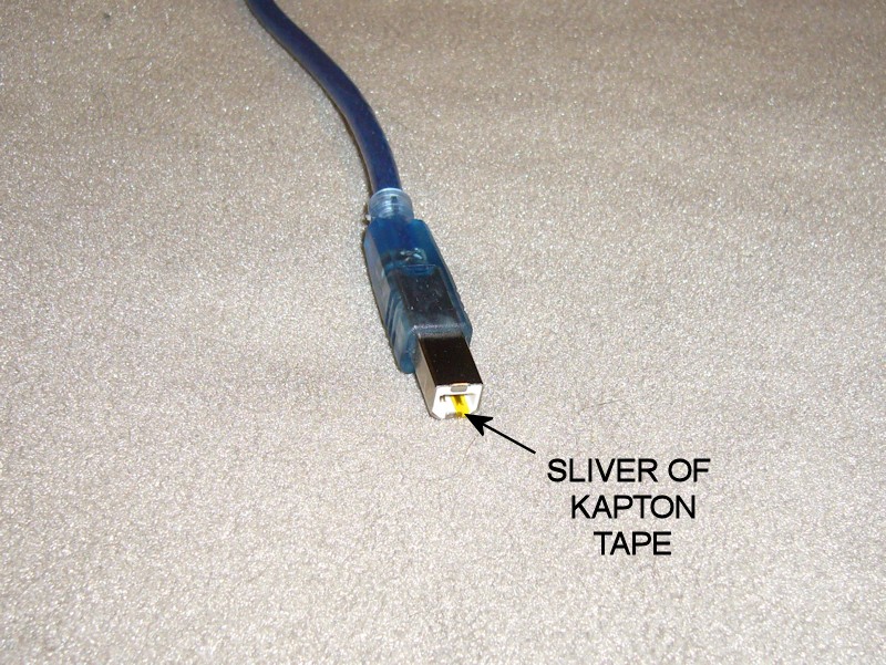
DISABLING POWER FROM USB
I've been one of those annoyed with how RAMPS stays powered up when the printer power supply is turned off but the USB cable is plugged into a host computer. A review of the MEGA2560 card indicated there's no jumper or other built-in means to change this. The board is designed so that if there is power on the USB connector, it will be used.
There's still a pretty easy fix for this - use a narrow strip of kapton tape to cover the 5V contact in the USB Type B connector that plugs into the RAMPS board.
Some USB interface designs require the 5V from the USB for at least the initial connection. The testing with the Arduino-type Mega2560 board in my i3v went OK without 5V being applied to the USB at all.
If you perform the mod, it might be a good idea to tag the cable as being modified in case the cable is reused for some other application later.
DISCLAIMER: The Arduino reference design for the Mega2560 board connects USB 5V to the UVCC pin on the ATMEGA16U2 USB interface chip. That pin no longer gets 5V with this mod, and the ATMEGA16U2 datasheet doesn't provide enough detail to understand what, if any, ramifications this may have. Also note that in a later post, a user observed erratic operation of his Auto Bed Leveling (ABL) servo with 5V removed from the USB cable, likely because the 12V-to-5V voltage regulator on the Mega2560 can't handle the extra 5V load from the servo. Implement this mod at your own risk.Last edited by printbus; 05-03-2015 at 11:04 AM. Reason: migrated to offsite image storage due to 3DPrintBoard issues

 Reply With Quote


Please explain to me how to...
05-17-2024, 12:15 PM in 3D Printer Parts, Filament & Materials