


Results 1 to 10 of 255
Hybrid View


-
01-02-2017, 08:07 PM #1Staff Engineer

- Join Date
- May 2014
- Location
- Highlands Ranch, Colorado USA
- Posts
- 1,437

PRINT BED REVAMP - INSTALLATION INSIGHT
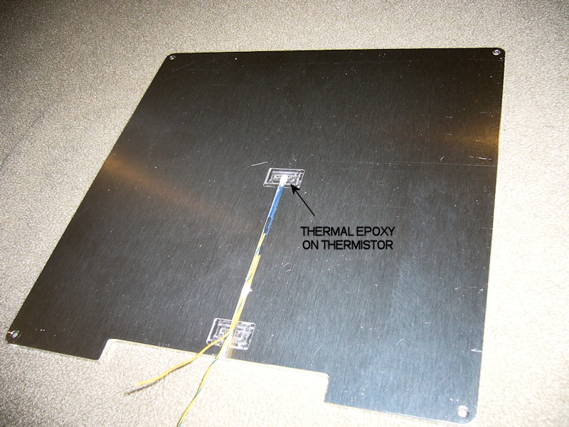
I reused the heat bed thermistor. I opted to splice short lengths of high temperature aerospace wire that I had on hand so the thermistor wires would extend off the aluminum plate. The wiring channel in the plate was cleaned of bits of loose metal and any oil from CNC machining. Dabs of Artic Alumina thermal epoxy from Artic Silver were used to bond the thermistor to the provided cutout in the back of the plate and to fix the wires into the routing channel. To ensure the thermistor was pressed against the plate as the adhesive cured, a short length of stick from a cotton swab was placed over the wire channel and temporarily held in place with a piece of tape. Not shown in the picture, a section of kapton tape was added over the larger thermistor cutout to act as a bit of insulator from the heater when it is installed.
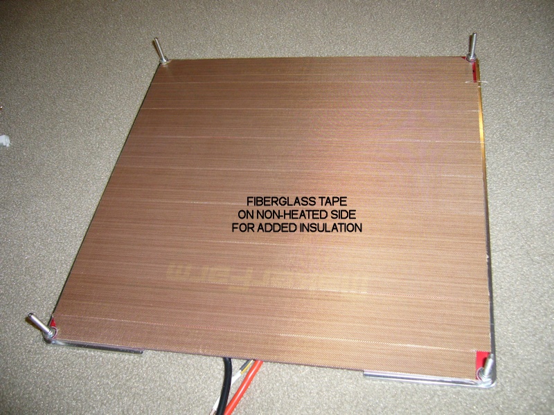
The MK1 heater was prepped by adding self-adhesive teflon and fiberglass tape to the non-heating side of the board. This was done just to provide some additional insulation on what is now the exposed side of the heater. I'll continue using the 8-inch square silicone trivet as the primary insulation between the heater and the wood y-bed.
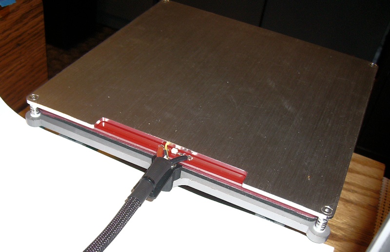
For inexplicable reasons, the strain relief attachment point on the y-bed for the 8-inch printer is *not* in the x-axis center of the y-bed. It's offset by 5 or 6mm, messing up a perfect view of what the wire routing should be from the wire attachment points to the strainrelief. To improve the wire routing, I scratched off the solder resist as required to provide new wire attachment points that meshed well with the thermistor wire channel (also offset from the center of the aluminum plate) and the surface mount LED I use as an informal monitor of what the heater circuit is up to. A special "high rise" strain relief bracket was created that moves the strain relief point off the far end of the y-bed.
I reused the MakerFarm y-bed springs rather than the thick silicone tubing that came with the aluminum plate. All four corner screws are locked in place with locknuts installed on the backside of the heater. From top to bottom the hardware stack-up consists of the M3 flat head screw, the aluminum plate, the heater, a nylon insert lock nut, the spring (which fits nicely onto the round part of the M3 lock nut), a custom printed (and currently unpublished) M3 shoulder washer, the wood y-bed, and thin M3 thumwheels. Like before, there are 10 notches around the thumbwheel, providing a somewhat calibrated 0.05mm height adjustment for each notch in thumbwheel rotation.
The PrintBite sheet was installed per Flex3D instructions, which includes two heated soak periods for setting the adhesive. I brought the forward edge of the PrintBite sheet as far forward as the y-bed travel would allow, and centered the sheet on the x-axis. I had ordered the PrintBite before I had finalized the rest of the revamp, and had opted to order the 200mm square sheet. To ensure a bit of margin on all sides, I've modified smoothieware and Simplify 3D to think I now have a 195mm limit in x and y. In a nutshell, my usable print area now follows the outer black line on the PrintBite markings.
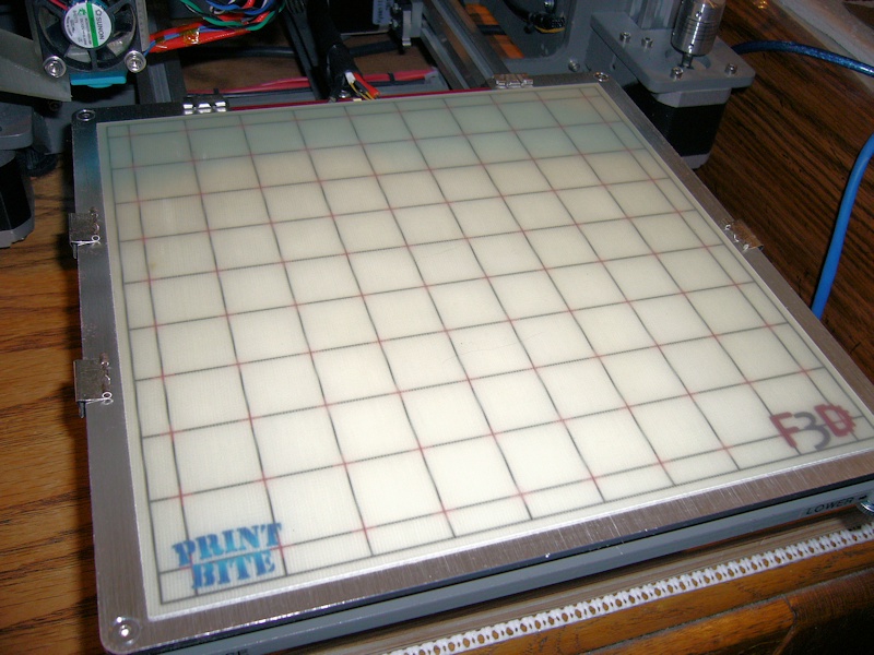
This provides a nice, flush surface to work with. I had smoothieware recalculate PID values for the heater control circuit, and updated the configuration text file accordingly. When I'd print with hair spray coated glass, I'd set the bed for 50 degrees C. Flex3d suggests increasing your bed temp by 10 degrees with PrintBite, so my recent prints on PrintBite have all been at 60 degrees. I've been getting great PLA adhesion with the bed set to 60 degrees, with most parts removable with some encouragement when the bed has cooled to maybe 45 degrees or so. I'm still tweaking, but have definitely been able to adjust for less first-layer squish than I used to. That's great for parts with a lot of first layer detail or something dimensionally important like a nut trap.
Yes, the picture reveals some binder clips. I've observed a bit of sagging between the aluminum plate and the heat bed on the sides, and mini binder clips are being used to eliminate the gaps. Whether the clips are there permanently is yet to be determined. Due to the additional height of the PrintBite print surface, I'm not as worried about anything catching on these binder clips, especially with the wings removed.Last edited by printbus; 01-03-2017 at 07:34 PM. Reason: why not?
-
02-02-2019, 11:50 AM #2Staff Engineer
- Join Date
- May 2014
- Location
- Highlands Ranch, Colorado USA
- Posts
- 1,437
Thanks for the feedback, Larry. Glad to know the build thread was helpful, and that it helped sink the hook as far as your interest in 3D printing.
I'm sure that if our kids were still home, we'd be printing a lot more. I haven't used any of them, but the range of filaments (silk, wood, marble, etc. ) out there is pretty amazing. Based on what I see in the various reddit and discord channels that I follow, the fine detail models that are available for cosplay, gaming, etc. is also incredible.
-
02-25-2019, 07:25 PM #3Staff Engineer
- Join Date
- May 2014
- Location
- Highlands Ranch, Colorado USA
- Posts
- 1,437
The X-carriage design has been published. See the "MakerFarm i3v/Pegasus X-Carriage for Bondtech BMG and e3dv6" item on Thingiverse at https://www.thingiverse.com/thing:3453439.
-
02-15-2020, 11:57 AM #4Student
- Join Date
- Jul 2015
- Posts
- 27
Hell Printbus, Originally Posted by printbus

It's great to see you still have your 8" MF i3v running. This is the same model I have which I just dusted off last week and got her running again after almost four years. She still functions well. After becoming re-acquainted with it I immediately became a bit tired of Greg's accessible extruder. While the printer serves my purpose for now making small ABS parts, I started searching to see if anybody upgraded their MF with a newer extruder. Can you comment on your experience with your Bondtech BMG?
-
02-16-2020, 09:17 AM #5Staff Engineer
- Join Date
- May 2014
- Location
- Highlands Ranch, Colorado USA
- Posts
- 1,437
Similar to RobH2, I only rarely use the printer these days - my time seems to continually get tied up in other things. With one exception, I've been pretty happy with the BMG. The big advantages are it's small, compact, and light. I do seem to have to level the print surface every time I print something, but only using the printer every few months could have more to do with that than the BMG and/or the associated carriage plate & hot end mount. Originally Posted by CoffeeCup
The one thing I miss from the Greg's Wade extruder is that the BMG has no easy way to release a filament. With the Greg's Wade, I'd heat up the hot end, reverse the extruder a few mm, and then release the grip on the filament so I could pull the soft filament out without the hobbed bolt pressing against the filament. With the BMG, you essentially have no choice but to keep reversing the extruder until the filament can be pulled from the gearing. There's a access lever you can unscrew that removes one of the gears, but the filament continues to press against the rear gear. I only rarely change filaments, so it isn't that big of a deal but it is something I don't care for.
If you opt to stick with the Greg's Wade, I'd definitely check out my remix of it. My research concluded the parts MF was shipping with the printer really weren't very optimal. The last Greg's Wade I printed was on my printer a couple of years before I swapped it out for the BMG approach.
On the rails vs. rods, yeah I don't know which provides a more rigid approach. I opted for the MF rail approach since what I read made me want to avoid linear bearings, and one of my goals was also to minimize the use of zip ties as mechanical fasteners on my printer. Seems that most printers using rods use zip ties to hold the linear bearings in place, and I didn't care for that.Last edited by printbus; 02-16-2020 at 09:18 AM. Reason: damned line spacing


 Reply With Quote


Qidi X Plus 3 Paper thin first...
05-27-2024, 01:15 AM in General 3D Printing Discussion