


Results 1 to 10 of 255
Threaded View


-
06-04-2014, 05:21 PM #10Staff Engineer

- Join Date
- May 2014
- Location
- Highlands Ranch, Colorado USA
- Posts
- 1,437

WIRE ROUTING (PART TWO)
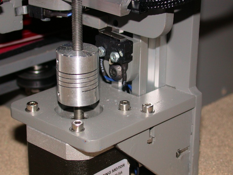
Z endstop switch wiring
Wires for the Z endstop switch were just dropped through the aluminum rail where they are bundled with the Z motor wires.
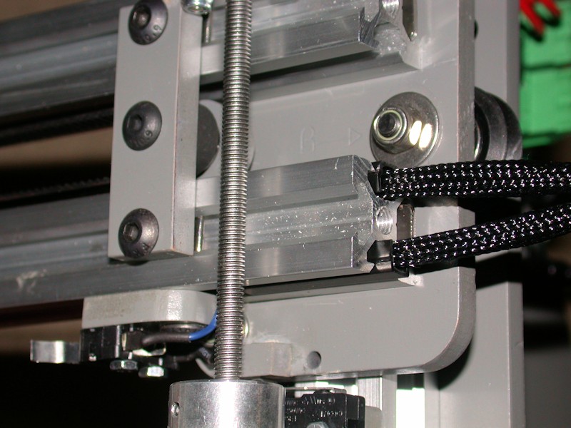
X Motor wiring
I fed the X motor wires to the other side of the printer through the top side channel in the lower X axis rail. A cut-to-fit slot cover keeps the wires in place. Sleeving extends from the motor to a few inches inside the rail.
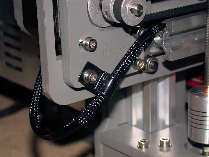
X endstop switch wiring
Other than adjustment access, there's nothing magic about the X endstop switch being on the top side of the X axis. For the cleanest wire routing, I moved it to the bottom and fed the wires to the end of the rail using the lower side channel. The X endstop wires and the X motor wires combine into a single bundle that loops around to the back of the printer. Note that moving the endstop switch required the switch to move to the other side of the endstop block.
FOLLOWUP COMMENT: After increasing the length of the notch in the endstop bracket, moving the X endstop switch underneath also allowed the switch to located a bit more to the right than would have been possible up on top. This was helpful in working to achieve the full 200mm printable area in the X direction.
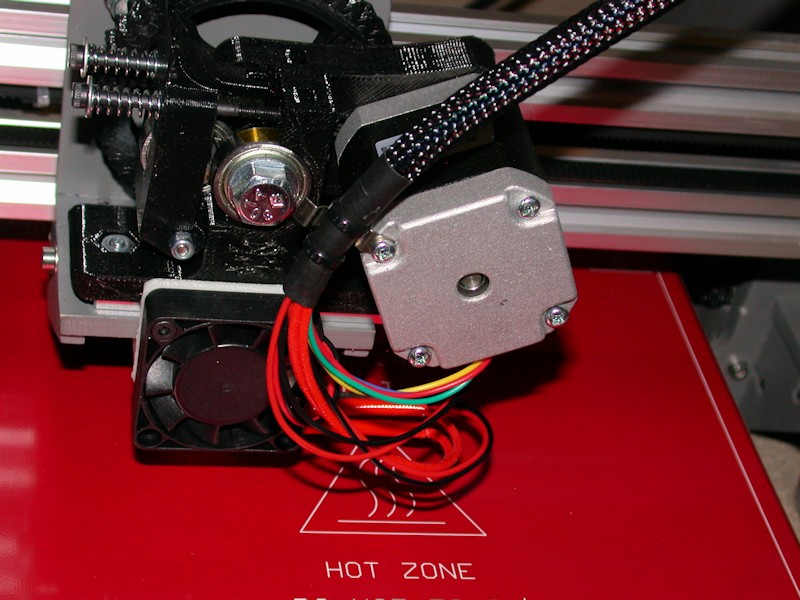
Extruder wiring
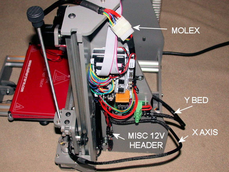
I used 3/8-inch sleeving over all the wires that are attached to the X carriage since 1/4-inch would have been a tight fit. The bundle is attached to the extruder motor using what I think is a spring contact from an old lamp assembly tore out of equipment eons ago. I could have used a cable clamp here, but would have to find an M3 x 45mm bolt to replace the 40mm one from the motor. The bundle of wires passes over the top of the printer. Immediately on the back side, the bundle passes through a Molex connector. The connector allows the extruder and cable harness to be removed from the printer. The current rating on the contacts should be more than adequate. (I'm in the process of reapplying the kapton tape and zip tie around the heater and thermistor wires - that's why they're not in the picture)
FOLLOWUP COMMENT: I didn't put the cable connector(s) at the extruder end since that would have added more weight to the extruder. More weight would mean more motor work is required to move the carriage around.
RAMPS Side View
Sufficient service loops were ensured for the X axis, Y bed, and extruder cables. Cable clamps used to ensure wire movements don't reach connector contacts, switch terminals, screw lugs, etc.
For misc low current 12v needs, I wanted something that was expandable to more loads and provided a means to easily disconnect loads when I wanted to do so. The 6x2 socket header is what I came up with using the parts I had on hand. In response to a later question, more info on this is here.
Last edited by printbus; 05-03-2015 at 07:17 AM. Reason: migrated to offsite image storage due to 3DPrintBoard issues


 Reply With Quote


New to 3d printing looking for...
05-20-2024, 12:56 AM in Tips, Tricks and Tech Help