


Results 1 to 10 of 255
Threaded View


-
06-04-2014, 05:07 PM #10Staff Engineer

- Join Date
- May 2014
- Location
- Highlands Ranch, Colorado USA
- Posts
- 1,437

WIRE ROUTING (PART ONE)
Although there are a few things I'd likely do different, I'm pretty happy with how the wiring and cable routing turned out.
FOLLOWUP COMMENT: In response to issues others have had in understanding how to wire the heat bed relay, I've tried to provide some detail in thread Clarifying i3/i3v heat bed and heat bed relay wiring
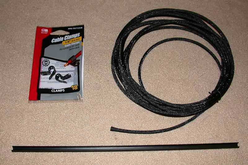
Materials Used
In addition to zip ties, I used (mostly 1/4-inch) expandable sleeving and a number of cable clamps to attach most of the wiring. Anyone who has used the expandable sleeving knows how frustrating it can be since it tends to unravel as soon as you cut it and try to feed anything through it. For this build I used "clean cut" sleeving I found on eBay that is a lot easier to work with. I also had obtained some aluminum rail slot covers from Openbuildpartstore. In addition to possibly being used for decoration, the slot covers can be used to create a wire raceway in the aluminum rails.
Every wire was custom fit to length, cutting off the connector and splicing it back on as required. I could have crimped new connectors on instead of splicing, but that would have required a lot of new contacts that I didn't have. Besides, almost all the heatshrink covered splices are now hidden inside the sleeving.
AC Power Switch
I added a push on/push off type power switch to the front of the printer.

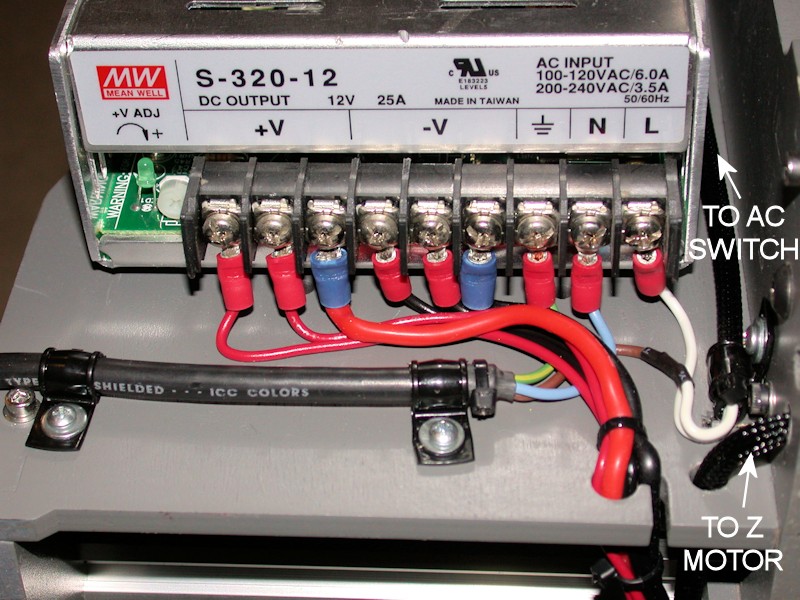
Power Supply Terminal Block
The power supply had three 12V and three return screws, so I routed three pairs of wires from the power supply to the other side of the printer. Heavy #14 wires were used for sourcing power to the heat bed relay. A dedicated pair of #18 wires provides power to the RAMPS board. An additional #18 pair fans out to low current loads like cooling fans and the LED lighting.
My power supply didn't come with any type of protective cover for the terminal block, so the AC connections are exposed. With time, I'll look into printing something to use.
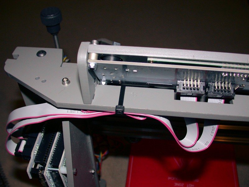
LCD Ribbon
I simply folded the excess ribbon from the LCD display and tied it to the upper member of the frame behind the LCD.
FOLLOWUP COMMENT: In the later GARBAGE DATA ON LCD DISPLAY post, I add a zip tie loop to pull the ribbon cables tight to the frame, away from the noise-laden bundle of wires from the X carriage that gets looped over the top of the printer. This helps reduce noise coupling into the LCD ribbon cables and messing up the screen.
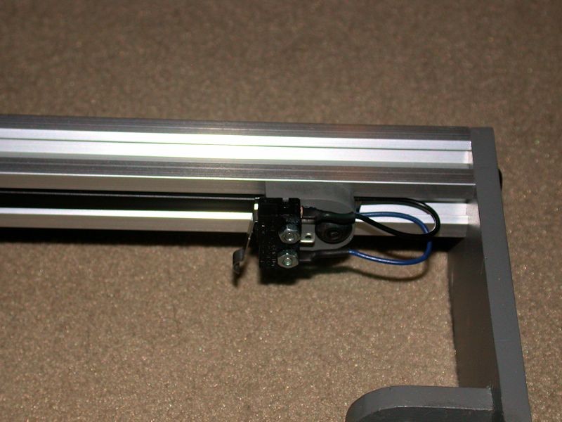
Y endstop switch wiring
Here I took advantage of the side channel of the aluminum rail and routed the wires through it. Wires are held in place behind a section of the black slot cover that was cut to fit. These wires get bundled with the wires from the Y motor at the back of the printer.
More routing info to follow... I've used up the five-pictures-per-post limit.Last edited by printbus; 05-03-2015 at 07:10 AM. Reason: migrated to offsite image storage due to 3DPrintBoard issues


 Reply With Quote


New to 3d printing looking for...
05-20-2024, 12:56 AM in Tips, Tricks and Tech Help