


Results 1 to 10 of 255
Threaded View


-
05-30-2014, 01:23 AM #11Staff Engineer

- Join Date
- May 2014
- Location
- Highlands Ranch, Colorado USA
- Posts
- 1,437

X Carriage Subassembly
X CARRIAGE SUBASSEMBLY
Yeah, another eccentric spacer where I added a fender washer.
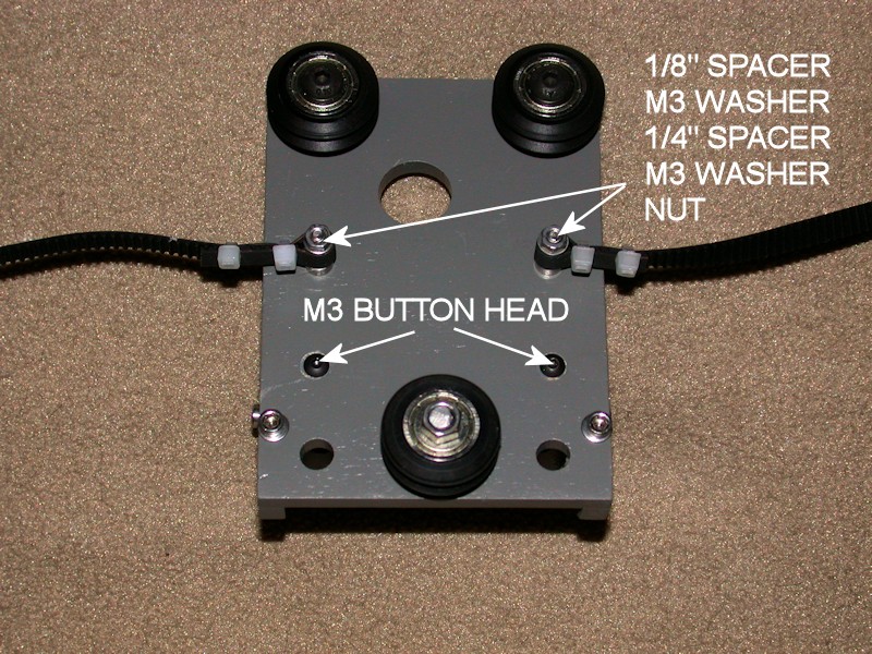
Being nitpicky about things, I didn't like how the belt is attached in the build videos. I don't like using multiple nuts on a bolt (can be hard to adjust and keep tight), and I wasn't sure wrapping the belt around an M3 bolt is consistent with the belt minimum bend radius spec. I admit I didn't try to search out what the minimum bend radius is, but I opted to wrap the belt around a 1/4-inch long aluminum spacer. The 1/4-inch length is close to the width of the belt. The stackup of hardware on the bolts is a 1/8-inch spacer, an M3 flat washer, the 1/4-inch spacer, another M3 washer, and a nut. I didn't have enough bolt length for a lock nut, so a standard nut with threadlocker was used instead. For appearance, I reversed the belt mounting bolts so the heads are at the front side of the carriage.
The build guide just says to use a 30 inch length of belt, with determination of the proper overall loop-to-loop length left to the user. I changed mine a few times, and likely ended up with about 28-1/4 inches between the center holes of the spacers on both ends. I doubled up the zip ties partially for appearance but also to help ensure several belt teeth are engaged on each end.
The X carriage is designed so that the heads of the bolts attaching the extruder bracket to the carriage clear the front facing channel of the lower X-axis rail. During my printer final assembly, I was seeing the bolt heads rub against the rail channel. This interference may have went away with final adjustments, but as a precaution I replaced those two bolts with button head types that have a lower profile head.
FOLLOWUP COMMENT #1: After mounting the extruder to the X carriage, I noticed the bolts mounting the top wheels were rubbing against the large gear on the extruder. This may have been driven by having to increase the number of spacer washers inside the large gear so the gear would clear the heads of the motor mounting bolts (for the added strength, I used longer bolts with heads and large washers that rest on the far side of the motor mount rather than the typical recessed bolt heads). I ended up shortening those bolts with a file by about 2.5mm so that the ends of the bolts are flush with the locknuts when tightened. See the later EXTRUDER AND HEXAGON HOT END post for a picture showing the interference.
FOLLOWUP COMMENT #2: Limit how much excess belt you have on the side that loops through the X idler, or the excess belt may get drawn into the idler bearings or pulley. Keep that side short, and put the excess belt on the other end.
FOLLOWUP COMMENT #3: During installation of the extruder onto the X carriage, the hot end tip couldn't get any closer than about 6mm inside the 200mm square marking on the heat bed. Part of the solution was to elongate the extruder mounting holes and the large U channel in the bottom of the X carriage to the right so that the extruder can be mounted closer to the X idler side. Next time, I'd elongate them as part of the initial X carriage build.
FOLLOWUP COMMENT #4: There are a few options on Thingiverse for alternate methods of attaching the belt to the x-carriage. My custom belt mount is available at http://www.thingiverse.com/thing:790207Last edited by printbus; 05-31-2015 at 08:16 AM. Reason: Added mention of alternate belt attachment


 Reply With Quote


New to 3d printing looking for...
05-20-2024, 12:56 AM in Tips, Tricks and Tech Help