


Results 151 to 160 of 189
Thread: Show your MODS
Hybrid View


-
03-25-2015, 08:39 PM #1Engineer

- Join Date
- Nov 2014
- Posts
- 522
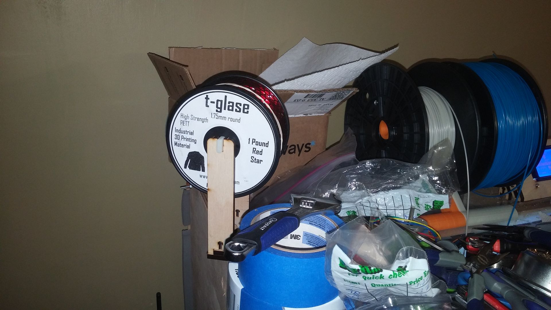
I made something very quick today, and it's available on thingiverse
http://www.thingiverse.com/thing:741218
A modification for the stock makerfarm spool holder to allow the use of Taulman spools.
-
05-11-2015, 12:37 PM #2Student
- Join Date
- May 2015
- Posts
- 3
My i3v 12" mods
Since this thread is about mods to the MakerFarm i3 I thought I'd share the ones I incorporated into my build. Besides using standoffs to mount the Rumba board instead the supplied bolts, I think the first one was to do away with the zip ties that hold the end stop switches. You gotta love zip ties, but when it comes to mounting these switches there had to be a better way. When rummaging through my parts bin I came up with a set of 2mm or 3mm bolts that fit perfectly, all I had to do was countersink the head into the plywood bracket.
Endstop.jpg
These new switches presented other problems as well, since the actuating arm is shorter than the old model I had to reverse the direction of the Y bed endstop so the "flag" is up, and add a piece of scrap plywood to the inside of the X carriage to actuate the switch .
After I began printing I noticed my build plate needed constant adjusting to stay calibrated, and the culprit was among other things loose bolts holding the concentric adjuster. According the build document you set the tension on these bolts like all the others, tighten the nyloc until you feel the bearing begin to bind and then back off a little. For me this didn't work all that well as the nyloc was barely engaged at this point and would eventually loosen up. This was remedied by swapping out the stock bolts for a longer versions and adding a nut between the bearing and concentric. This made several improvements possible at once because now the bearing rode on the shank of the bolt rather than the much smaller threaded portion, and I was able to adjust the two parts individually.
IMAG2529.jpg
Another modification to the Y-Bed was to do away with the spring loaded adjustments for the build plate and go with a solid mount. As before longer bolts were substituted and locked in place with nuts. A simple lock nut system was employed to both adjust and hold the heat bed in position, once set they do not move. I reused the springs since they provide just enough resistance to hold that lower nut in place.
Heatbed.jpg
I also added an inch of fiberglass insulation to this after my first Y-Bed warped beyond repair. This may be particular to the 12" model because of the larger heat bed and Y-Bed, in any case MakerFarm has already come out with a mod to help address the issue.
After untold hundreds of filament jam and weeks of frustration I was finally able to resolve the issue..it seems that not all Hexagons are created equal and I happen to get one of those. While I was clearing yet another jam I noticed that after I had reassembled the hot end the barrel and nozzle hole were slightly out of alignment. Chamfering the lead of the nozzle resolved the problem but not before I redesigned the extruder and hob bolt. I had tried using a small tube to take up the slack in the oversized hole of the extruder, and that helped to some degree. I wanted a more permanent solution so I modified the extruder stl file so that it fit the 1.75mm filament...I know this design is supposed to be a one size fits all, but I'm not convinced that's the right way to go. Here is a MakerFarm branded extruder designed for 1.75mm filament.
1.75mm Extruder mod(2).stl
I also made a hob bolt to fit this filament and I was surprised at how easy this was. I used a previously printed extruder block to hold the 5/16 bolt in place with bearings on both ends so that it turned freely. I then used a Dremel tool and large cut-off wheel to notch the bolt in exactly the right spot. To make the teeth I took a new hack saw blade and set it in the groove, and with lots of down pressure began to roll the bolt back and forth with the hacksaw blade. In just a few minutes the teeth began to take shape and once I was satisfied with the results installed my new hob bolt...it's been working flawlessly ever since.
And lastly I modified the fan shroud to keep the hot end hot...the stock one was too short in my opinion and made keeping the temperature of the hot end up during large prints almost impossible.
ExtendedShroud.stl
Those are my simple mods.. I hope some of you find them useful.
MikeLast edited by midnitmike; 05-11-2015 at 12:48 PM.
-
01-14-2016, 11:51 AM #3Student
- Join Date
- Mar 2015
- Location
- Yes
- Posts
- 15
Howdy all,
I was having horrible warping problems when printing ABS. From this great forum I learned that the root cause of my warping issues was cold, my printer lives in my workshop in the garage and tho heated was way too cold for things to print properly.
I decided to build an enclosure for my i3v 8 inch printer. I started with a simple cardboard box lined with aluminum foil as a test, and it worked wonders my prints improved by leaps and bounds.
I then decided I needed to build a prettier enclosure this is the result:
IMG_4123.jpg
It's made from 3/4" aluminum angle for the frame the side panels are 1/4" foam board with aluminum foil glued to the inside faces. The corner pieces and the hinges are 3d prints designed by me. I'm pretty happy with the result it holds heat well and though compact everything fits where i wanted.
IMG_4124.jpg
IMG_4127.jpg
IMG_4129.jpg
IMG_4131.jpg
Thanks for looking.
-
01-14-2016, 12:13 PM #4Technologist
- Join Date
- Oct 2014
- Posts
- 134
Very nice work.
-
01-14-2016, 02:28 PM #5Super Moderator
- Join Date
- Nov 2013
- Location
- Baltimore, MD
- Posts
- 897

Very nice enclosure. Great touch to move the display to the door. Did it completely solve the warping on that same part, meaning, was all the nice hard work worth it?
Bambu P1S/AMS
NVision4D http://nvision4d.com
-
01-14-2016, 04:16 PM #6Student
- Join Date
- Mar 2015
- Location
- Yes
- Posts
- 15
Thank you. As for knowing if the enclosure will eliminate or at least greatly reduce warping, only time will tell. I haven't had a chance to calibrate my printer yet to test it properly. I did run a small test print after stuffing it in the enclosure however, and it didn't warp at all; print quality was pretty sub par though. Originally Posted by RobH2

-
01-14-2016, 04:26 PM #7Super Moderator
- Join Date
- Nov 2013
- Location
- Baltimore, MD
- Posts
- 897
No doubt it's going to help. ABS warps so badly that I've switched to PET, but, you give up smoothing with Acetone. As dangerous as that is, it's still less dangerous and the chemicals to smooth PET. Lately I've even had bad warping with PET and it really is warp friendly. So, I'm thinking about an enclosure too. That's the reason I ask. I don't want to go through all the work and still say, "crap, that warped." I'll be curious to hear more results from you. I'd like to see if you can print that same part in ABS exactly the way you did before you built the enclosure and see if the warp is mitigated.
Bambu P1S/AMS
NVision4D http://nvision4d.com
-
01-14-2016, 04:31 PM #8Senior Engineer
- Join Date
- Jun 2014
- Location
- Burnley, UK
- Posts
- 1,662
I closed my Wanhao and stuck a hair dryer in, removed the heated bed and connected the hair dryer to the conections (through a relay) ABS never warps at all now.
-
01-15-2016, 12:18 AM #9Engineer
- Join Date
- Jul 2014
- Location
- Eastern Colorado
- Posts
- 536
I, too, am designing an enclosure for my printer, as it's getting relocated to the basement. I don't have any materials yet, just the plans. It'll be made out of 3/4 inch plywood, all the electronics mounted on the outside, with a RaspberryPi for printer control, camera and web access.printerbox4.jpgprinterbox2.jpg
The printer will be mounted to a square of plywood which can slide in and out of the box for maintenance. Lights and a webcam will be on the inside so prints can be monitored without needing to open the box. Internal dimensions will be 2ft cubed, plus a little extra in the Z to accommodate the printer shelf. I intend to have some flexible tubing connecting to the rear of the box and to the hotend fan to prevent overheat jams.
-
01-16-2016, 04:06 AM #10Student
- Join Date
- Jan 2016
- Posts
- 4
Hello
new to this forum; got a 10" pegasus recently and figured I'd share what I've done so far.
I configured Marlin 1.1.0 RC3 for it; if anyone else has a pegasus I'm maintaining my updates here: https://github.com/quixotic120/MFMarlin . I also maintain a log of my mods there with images where appropriate: https://github.com/quixotic120/MFMar...ee/master/mods
First mod was the endstops; drilled the mounting holes out to 3mm and bolted them down instead of using the zip ties. I also removed the roller bars because I found them to have a bit too much play, however I would suggest leaving it on the Y axis because the play doesn't matter as much there and its a pain to align without the bar.
I cleaned up the power supply a bit after that; added a C14 socket with switch for the power cable and printed an endcap/mounts for the PS
I then replaced the cruddy plate glass I got initially with 3mm borosilicate. With this I fashioned new clamps out of ring crimps that fit under the screws on the corners of the heat bed. I retained the binder clips but went with much smaller ones (~10mm from edge of bed) because the heat bed was not making good contact with the glass but I might replace these with firmer insulation.
next I printed a new fan shroud that uses 1 40mm fan instead of 2 30mm fans (dual extruders). This was unintentional; it was because I am dumb and broke fins out of both 30mm fans by accidentally hitting them. They still spun but were out of balance and made a horrid noise. I went with 40mm because I had that on hand over buying more 30mm fans. I also added a fan guard to avoid this repeating itself. I'm going to probably redo this later as the fit is not ideal. While I was doing this I added an 80mm fan to my ramps board.
I added lighting at this point and started really cleaning up the wiring. The lighting is basic, a few LEDs around the frame with an SPST switch. The wiring is definitely much better but still kind of crappy.
The last two weeks I went on a bit of a tear: I got lucky at micro center and arrived right after they took a delivery of raspberry pi zeros so I set up octopi plus a case. Trying to find time to set up a camera I just got too. I had ordered some stuff that finally came in so I also set up auto bed leveling with a servo (as per zennmaster's guide), added an SSR to allow PID control of my heat bed, and replaced my z-rod brackets with an anti-backlash mount I found on thingiverse.
Next I want to build an enclosure and I'm also looking at replacing the threaded rods with lead screws but I'm not sure if thats worth the money. My threaded rods are super wobbly though.

 Reply With Quote


Qidi X Plus 3 Paper thin first...
05-27-2024, 01:15 AM in General 3D Printing Discussion