


Results 11 to 20 of 103
Hybrid View


-
05-05-2021, 10:41 AM #1Super Moderator

- Join Date
- Jul 2014
- Posts
- 8,816
what he said :-)
I have to say, give me a cheap physical switch endstop over an optical any day.
My k40 laser has optical endstops. And even with a metal piece going into the slot - it didn't work till i'd bent the metal so that it was exactly in the middle of the slot.
But for some reason they are considered to be superior to normal endstops. Go figure.
And for gods sake: cheer up !
You got a helluva printer at a bargain price and amazon even gave you free money into the bargain !
What's a couple tiny little niggles ?
Sheesh - you do know that electronics are effected by excess negativity. It's all down to the quantums doncha know :-)
So cheer up and start beaming happy thought at the poor beast.
-
05-05-2021, 11:46 AM #2Staff Engineer
- Join Date
- Jul 2016
- Location
- South Florida, USA
- Posts
- 1,248

My 3 color mixing printer has used optical endstops since it creation in 2016. I print flags for them to mount to the extruder and to the heated bed and adjust where home position is by the length and size of flag I print. It is incredibly reliable and I have never had a moments trouble with this setup even with the cheapest optical sensors I could find. Because it is optical, it is touchless, or rather it never takes wear so in theory it will stay in the exact condition it was in when you installed it always and forever. Here is my X endstop setup. You can clearly see when the extruder homes the flag will enter the optical endstop on the X motor housing..
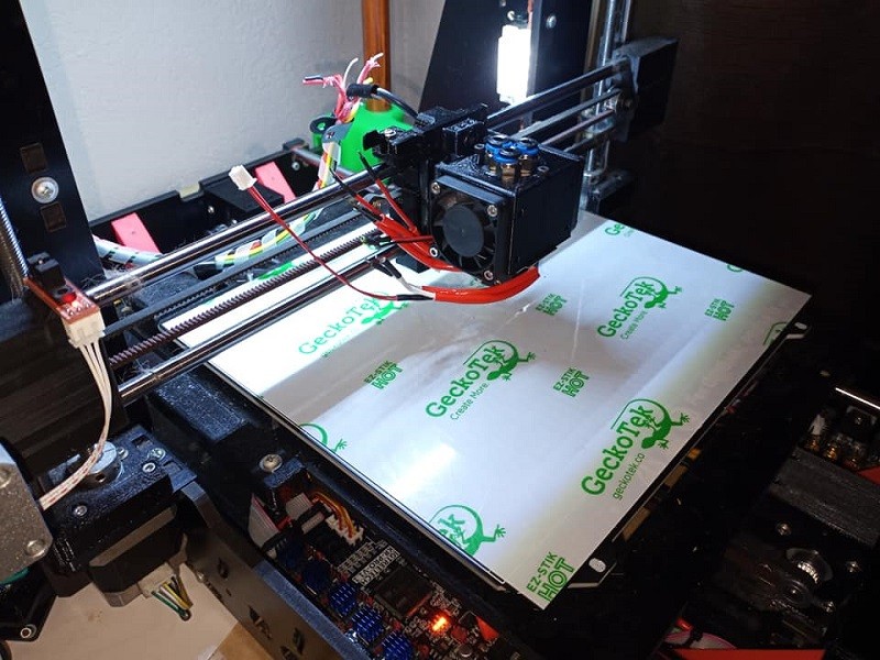 I didn't see a flag anywhere in any of your pictures.
-
05-06-2021, 11:53 AM #3Staff Engineer
- Join Date
- Jun 2014
- Posts
- 885
Unless you're strapped for time, it seems more practical to return for replacement and hope you get one that works.
-
05-06-2021, 12:01 PM #4Technician
- Join Date
- Apr 2021
- Posts
- 70
Normally no doubt. Originally Posted by fred_dot_u

But in this case the purchase was an Amazon warehouse team item "acceptable" condition dropping the price to $441 dollars. Any return is for reimbursement only...no replacement. I've gotten spouse acceptance of a $500 3d printer budget after years of lobbying. so if I return it, I may be faced with some tough choices.
-
05-06-2021, 03:48 PM #5Super Moderator
- Join Date
- Jul 2014
- Posts
- 8,816
smile, everything is better when you smile :-)
I'm gonna nickname you moriarty:
Best war film EVER made !
But yep test the stops.
You know you have one fully working.
so try it on the non-working side.
If it works - great, just a dud endstop.
If it doesn't - use a bit of tape and make the tab a little longer.
If it still doesn't work.
THEN you can make with the negative waves ;-)
-
05-07-2021, 10:02 AM #6Technician
- Join Date
- Apr 2021
- Posts
- 70
Well crud... Originally Posted by curious aardvark
Somehow I hadn't noticed that each of the optical sensors has a faint white panel that lights pink when the unit is powered on. These are clearly visible on the z-axis. When I tried out the removed "bad" left side E1 X-axis on the E2 right side connector I immediately noticed that it lit up pink at power up. it also passed the homing operation test. Of course my heart sunk. That is not a good result. I connected it back to its proper connector on the E1 side to be sure I hadn't missed that glow earlier and noticed it blinked a few times after power up. It turns out that fiddling with the long base unit left side connector cable bundle makes the sensor light blink on and off as it apparently has a loose finicky connection. If there is any cable connection on this thing that needs to be robust in every way and not all loose it is probably these left and right cables given their huge range of motion and the fact that, unlike the extruder cables, they cannot readily be replaced or swapped out with replacements.
I am not sure what I should do. On the one hand the new sensor will clearly not solve anything. On the other hand I have no idea as to how difficult a loose wire connection is to troubleshoot. I can package the whole thing up. print out my return labels and send it all back to amazon at no shipping cost (prime benefit) for a refund and buy a new one direct from Tenlog with at least a 1 year or more warranty but at an additional cost of at least $150 more and potential of attempted spouse veto on the whole project....Or I can try to tackle this loose wire project somehow.
On the Brightside, technically we no longer have any reason to suspect mainboard fault even if we still have to call it a base unit fault.
-
05-07-2021, 10:29 AM #7Staff Engineer
- Join Date
- Jun 2014
- Posts
- 885
I don't think your heart needs to sink, as you've provided a focus, narrowed things down nicely.
If the results of moving the "bad" sensor to the other side is that it suddenly becomes "good," you won't have too many variables to address. Making a guess on your connectors, I would suggest to examine that all leads of the specific connection to ensure the tiny metal prongs inside the plastic housing are pushed fully into the housing. The metal prongs are slightly spring loaded and the back side has a finger that sticks up in the opposite direction. When the prong is pushed into the housing, the finger pops up into a recess, preventing back travel. If the finger doesn't get fully into the recess, the prong can be pushed backwards when the connection is made.
If that doesn't solve the problem, you could have a cold solder joint. Those can be visibly obvious but can also be invisibly "un-obvious" and require a touch with a hot soldering iron to resolve.
It's best if you can identify the specific wire and the contact points at each end. It's apparent that the module assembly is in acceptable shape if you can move it completely from one side to the other. That leaves the connector into which it plugs (or is it a sub-board) on the way to the main board?
More details about the cable routing and connectors involved would be helpful. Photos might be helpful but not necessarily, as it could be challenging to get suitable detail amidst a bundle of wires. Photos of the connectors involved in the circuit would be good.
-
05-07-2021, 10:42 AM #8Technician
- Join Date
- Apr 2021
- Posts
- 70
Fiddling seems to show the bad connection is just inside where the wrapped bundle of cables enters the case. Immobilizing all movement of the wires within the cable bundle at any point close to the base unit almost halts the blinking out of the LED even with lots of fiddling downstream of the immobilization point whereas any slight movement upstream of the immobilized wires (towards the base unit) causes tons of blinking and great difficulty getting it to light again. I would almost be tempted to just attempt to immobilize the wires near the base except that the large range of motion demanded by the attached bridge would probably defeat any immobilization scheme and I'm not sure if there would be enough slack left over for normal operation and finally any small vibration would probably still break the sensor connection (probably with infuriatingly stupid timing) and really make me regret relying on that solution. So, I'm thinking I need to open the case, inspect the cable connections for obvious opportunities to fix and if nothing can be done there, close up the patient note time of death and print up my RMA labels. Originally Posted by fred_dot_u
-
05-07-2021, 11:29 AM #9Technician
- Join Date
- Apr 2021
- Posts
- 70

Ok! Seven underside screws gets you into the case of the TL-D3 Pro. The cable connections are not soldered which is helpful but I do not have a replacement handy and do not see an obvious break. Wires can have internal breaks quite easily so ordinarily I'd assume replacement is my only prudent option unfortunately. Although, note in the closeup that X1 is the only sensor wire that will have to thread a path under the mainboard should I attempt to replace the whole wire, probably necessitating lifting the mainboard. Also, unlike the other neighboring 4 optical sensor cable connectors to the mainboard the x1 optical sensors connector to the mainboard is wiggly in the socket. Surely I can assume that is the cause of the loose connection in this case? Can a loose socket be repaired? I've tried just snapping it back in with no luck but I also don't see any sign of broken plastic in the socket.
Last edited by minneapolis-matt; 05-07-2021 at 11:37 AM.
-
05-07-2021, 12:11 PM #10Staff Engineer
- Join Date
- Jun 2014
- Posts
- 885
I'm not sure which is which in the photos, but if the limit switches/sensors are in the upper right of the second photo, it gives me a clean view of the connections. You have a couple useful tasks ahead.
Identify the working sensor wiring and swap it for the non-working connection. For this, you're really only looking for the steady LED at this point, as you don't want movement or want to keep things to a minimum. Swapping at the board will give you a better reference. If suddenly the good one goes bad, it's on the board, which is the more likely circumstance. That will be confirmed if the bad one goes good, obviously.
Examine the connectors as you remove them, perhaps tugging on the individual wires that enter each connector. If any single wire moves freely and/or comes out of the connector, that's a good/bad sign. Good that you found it and will fix it.
With everything connected in the usual manner, push on the socket for the bad sensor connection. If there's a cold solder joint on the board inside the socket, this may create the intermittent connection. It's an easy fix if you have a cold solder joint, but the labor in disconnecting everything isn't all that much fun.
You suggest that wires can have internal breaks, but it's been years since I've come across such a failure. Your printer would have to have been misused and many years older for that to be high on the list. I won't reject it outright, but it's less likely than a cold solder joint or a loose prong inside the connector.
Do you have a digital multimeter and/or a soldering iron? Either are pretty inexpensive if you buy cheap, but if you plan to be a 3D printer mechanic (plan for it), you'll want a decent DMM and a soldering iron with a couple different size tips in the 25-40 Watt range.


 Reply With Quote


New to 3d printing looking for...
05-20-2024, 12:56 AM in Tips, Tricks and Tech Help