


Results 31 to 40 of 255
Hybrid View


-
06-01-2014, 08:43 PM #1Engineer-in-Training

- Join Date
- Feb 2014
- Location
- CT
- Posts
- 345
Great build Kevin. In the end you will have a great printer that will improve with every Hey honey are you heading to the hardware store again..

-
06-02-2014, 07:17 AM #2Engineer-in-Training
- Join Date
- Mar 2014
- Location
- USA
- Posts
- 388

printbus, good to see that you're taking you time and enjoying the build! I had a great time building mine, but it seems like you're having an ever greater time! haha

I'm intrigued by your led strip lighting on the bottom of your x carriage. I have the same strip lighting on hand and I'm very interested in seeing how yours turns out when the lights are on during a print!
-
06-02-2014, 07:34 AM #3Staff Engineer
- Join Date
- Oct 2013
- Location
- Narellan, New South Wales, Australia
- Posts
- 912
I've fitted the same sort of thing to my printer. I'll post some pix tomorrow. Originally Posted by gmay3

OME
-
06-02-2014, 07:35 AM #4Engineer-in-Training
- Join Date
- Mar 2014
- Location
- USA
- Posts
- 388
Awesome! Thanks OME!
-
06-04-2014, 05:21 PM #5Staff Engineer
- Join Date
- May 2014
- Location
- Highlands Ranch, Colorado USA
- Posts
- 1,437
WIRE ROUTING (PART TWO)
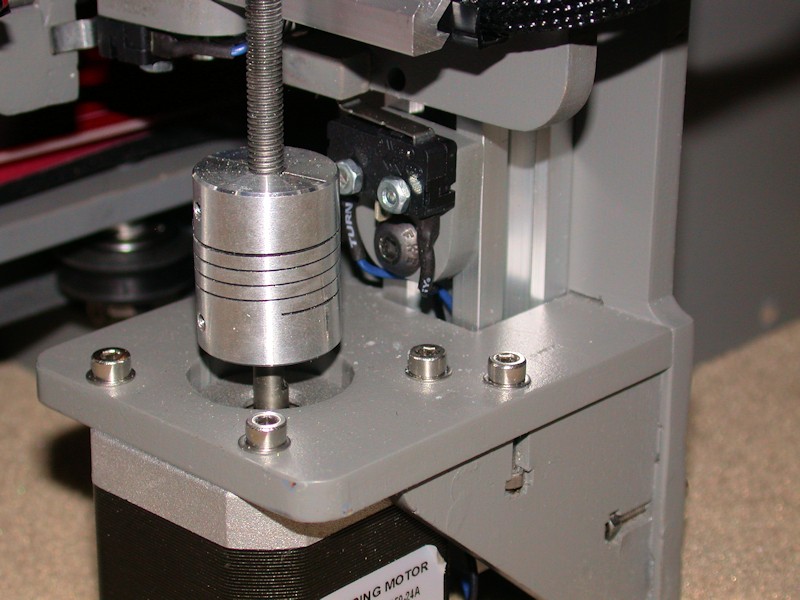
Z endstop switch wiring
Wires for the Z endstop switch were just dropped through the aluminum rail where they are bundled with the Z motor wires.
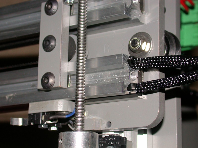
X Motor wiring
I fed the X motor wires to the other side of the printer through the top side channel in the lower X axis rail. A cut-to-fit slot cover keeps the wires in place. Sleeving extends from the motor to a few inches inside the rail.
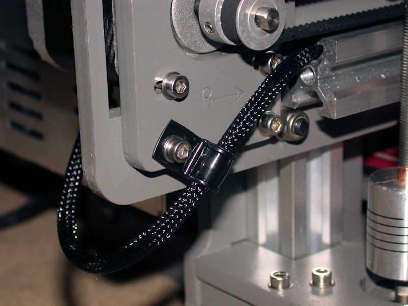
X endstop switch wiring
Other than adjustment access, there's nothing magic about the X endstop switch being on the top side of the X axis. For the cleanest wire routing, I moved it to the bottom and fed the wires to the end of the rail using the lower side channel. The X endstop wires and the X motor wires combine into a single bundle that loops around to the back of the printer. Note that moving the endstop switch required the switch to move to the other side of the endstop block.
FOLLOWUP COMMENT: After increasing the length of the notch in the endstop bracket, moving the X endstop switch underneath also allowed the switch to located a bit more to the right than would have been possible up on top. This was helpful in working to achieve the full 200mm printable area in the X direction.
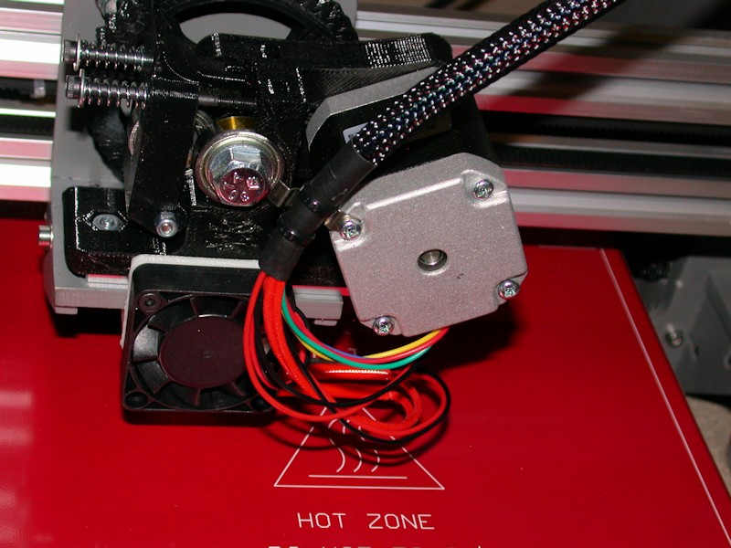
Extruder wiring
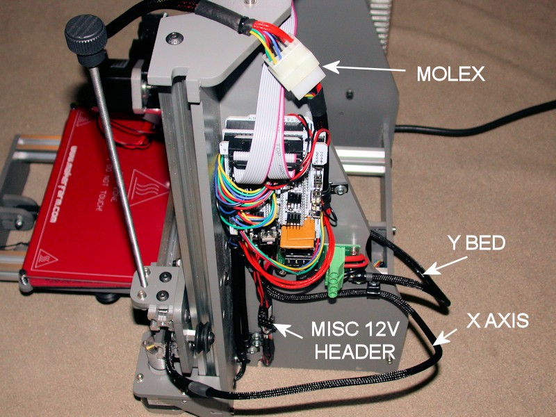
I used 3/8-inch sleeving over all the wires that are attached to the X carriage since 1/4-inch would have been a tight fit. The bundle is attached to the extruder motor using what I think is a spring contact from an old lamp assembly tore out of equipment eons ago. I could have used a cable clamp here, but would have to find an M3 x 45mm bolt to replace the 40mm one from the motor. The bundle of wires passes over the top of the printer. Immediately on the back side, the bundle passes through a Molex connector. The connector allows the extruder and cable harness to be removed from the printer. The current rating on the contacts should be more than adequate. (I'm in the process of reapplying the kapton tape and zip tie around the heater and thermistor wires - that's why they're not in the picture)
FOLLOWUP COMMENT: I didn't put the cable connector(s) at the extruder end since that would have added more weight to the extruder. More weight would mean more motor work is required to move the carriage around.
RAMPS Side View
Sufficient service loops were ensured for the X axis, Y bed, and extruder cables. Cable clamps used to ensure wire movements don't reach connector contacts, switch terminals, screw lugs, etc.
For misc low current 12v needs, I wanted something that was expandable to more loads and provided a means to easily disconnect loads when I wanted to do so. The 6x2 socket header is what I came up with using the parts I had on hand. In response to a later question, more info on this is here.
Last edited by printbus; 05-03-2015 at 07:17 AM. Reason: migrated to offsite image storage due to 3DPrintBoard issues
-
06-14-2014, 06:12 AM #6Staff Engineer
- Join Date
- May 2014
- Location
- Highlands Ranch, Colorado USA
- Posts
- 1,437
WRAPUP COMMENTS ON THE INITIAL BUILD
After completing about a dozen items and calibration prints, I'm pretty content with my decision to build the i3v. It appears to be very capable, yet obtained at the lower end of the price range for 3D printers without having to gamble on a crowdfunding effort. Yeah, I spent a lot of time building it, but I knew I would going in. Others have shown you can get an i3v functional without as much extra effort. For the long haul, I know I've got good support available at MakerFarm, and the parts are mostly generic and available elsewhere.
I found it extremely helpful for MakerFarm to have provided configuration files for Slic3r and for the electronics to arrive preconfigured with firmware for the i3v. This allowed me to get the printer up and running without having to fret over configuration and firmware download details that I wouldn't have understood at the time. I can now work through them as I learn more about printing and the i3v printer.
KEY BUILD POINTS
Expect to use the MarkerFarm build guide and build videos only as a guide. Don't assume they tell you everything. Think about what you're doing, and be ready to fill in the missing details yourself. Post questions on the board here or contact Colin. I only asked him two questions, and got responses quickly.
Watch for hardware fit conflicts. Some things won't fit if adjacent nuts aren't rotated right. I had some X carriage screw heads rubbing on the X axis extrusions, and had issues with the length of the bolts on several of the X carriage and X idler wheels. Several holes required elongating. This may be more personal opinion than fact, but work to eliminate any mechanical slop in the hot end tip when you have the extruder done. It seems to me that you can't expect good prints if the hot end tip isn't fairly rigid.
DESIGN CONCERNS
Here are my concerns with the i3v design, regardless of whether they're systemic to the Prusa i3 or specific to the MakerFarm i3v. While I call them concerns, remember I'm still happy with the i3v. Resolving these issues would make the thing pretty perfect as far as I'm concerned.
- Adjusting bed clearance with the Z endstop switch and a fixed spacer between the heatbed and Y bed at the home corner. What a pain. Leaving the endstop position alone and adjusting the heatbed height at all four corners is perhaps the best mod I did to the i3v.
FOLLOWUP COMMENT: Clough42 has been posting great things for the i3v on Thingiverse, including parts for a screw-based Z-stop adjustment.
- Lost capacity in the X axis. The X motor mounting plate limits how far the X carriage can move to the left. I had to get creative to find ways to allow the extruder to move farther to the right in order to achieve the specified 200mm range in the X axis. Why couldn't the X axis aluminum rails be a bit longer and the frame stretched a few mm to resolve this?
- Rinky dink approach to the Y idler that requires tinkering if you don't want the belt rubbing on the wood brackets. Issues here are exaggerated by misalignment between the Y bed belt mount and the Y idler. Why don't they line up better? The X idler design is similar, but at least there it's easier to adjust the angle of the bolt holding the pulley bearings as a belt adjustment.
FOLLOWUP COMMENT: A custom belt guide wheel has recently been added to Thingiverse, with an improved one at http://www.thingiverse.com/thing:790138. This would resolve the Y idler concern, and could also be used on the X idler.
- There are worrisome places I can see the wood plates flex. Pressing back on the Y idler front just a bit causes the Y belt to sag. If I manipulate the Z motor cases by hand, I can see the frame sidewalls flex. Maybe neither is significant, but reinforcements could have been readily added to prevent both. I'll also be watching for warping in the Y bed since it's always under stress from the heat bed springs.
Last edited by printbus; 05-31-2015 at 08:34 AM. Reason: migrated to offsite image storage due to 3DPrintBoard issues
-
08-12-2014, 10:08 PM #7Engineer
- Join Date
- Jul 2014
- Location
- Eastern Colorado
- Posts
- 536
Could you post more details about this? Originally Posted by printbus
-
08-13-2014, 07:47 AM #8Staff Engineer
- Join Date
- May 2014
- Location
- Highlands Ranch, Colorado USA
- Posts
- 1,437
Here's an additional picture that didn't make the picture limit for the original post. A pair of heavier gauge wires from the power supply is fanned out to individual pins in a 5x2 configuration socket header - like you would use to plug onto rows of pins on a circuit board. Wire-wrap length header posts are broken into two pins each and used to provide connection between the 5x2 header and individual socket headers for each fan, etc. Wire wrap length posts are used since they are long on both sides of the plastic block holding the pins. A bit of CA glue can be used to attach the header post part to the connector going off to wherever. This isn't the most elegant, but I wanted something that was quick and easy to change connections at and had to be made from parts I had on hand. I didn't want to wait another week for parts to arrive before I could power up. Originally Posted by AbuMaia
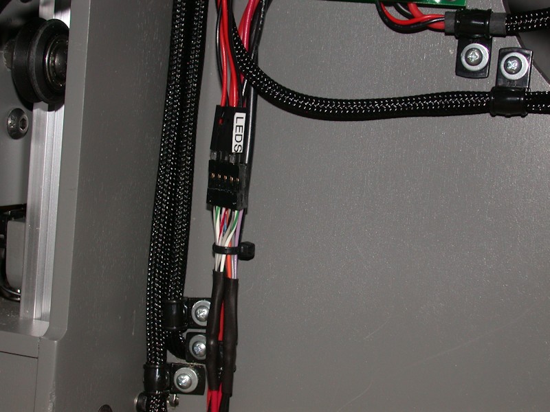
I'm always short on the socket contacts for these connectors. On a couple of things I've since added, I drilled out the holes in the 2-pin shrouds a bit so wires could pass through them, carefully soldered the wires directly to the short side of standard circuit board length header posts and then slipped the shroud down to cover the solder connections. A dab of glue keeps the shroud in place.Last edited by printbus; 05-03-2015 at 07:37 AM. Reason: migrated to offsite image storage due to 3DPrintBoard issues
-
09-03-2014, 11:09 AM #9Staff Engineer
- Join Date
- May 2014
- Location
- Highlands Ranch, Colorado USA
- Posts
- 1,437
NOISE AND VIBRATION REDUCTIONS
Several changes have been made to reduce vibrations and other noise sources from the printer. Almost every print can reveal new causes, depending on print sizes, travel speeds, etc.
OPERATIONAL CHANGES
Although I've made some mods to reduce vibrations, some of the improvements are just in how I use the printer.
Following clough42's recommendation of setting retraction speed to 10mm/sec had a side benefit of reducing noise considerably. I'm not sure if the extruder motor was skipping before or what, but 10mm/sec causes retraction to be smooth and quiet now.
FOLLOWUP COMMENT: After digging into motor capabilities and limitations, I've increased my retraction speed to 15mm/sec.
When I was using slic3r as my slicer, I learned to orient prints that have a lot of infill on the bed so I could set linear/rectilinear infill orientation angle to 0 instead of the normal 45 degrees. 45 degrees causes the X and Y motors to be alternatively stepped to accomplish the diagonal movement. 0 degrees allows linear/rectilinear infill to be accomplished with single-motor movements in the X-axis or Y-axis direction across the entire print. The first time I bumped into this with the long top-side spool mount brackets printed diagonally on the bed, I was very surprised in how much quieter the print went. Unfortunately, Cura forces all infill to be at 45 degrees, so I don't have that option when I'm using it.
PRINTER MODS
One of the more surprising vibrations I tracked down was on the RAMPS board. It turned out to be the two square yellowish plates (polyfuses) by the power entry block. They were touching, and would rattle under certain conditions. A dab of hot glue added between the two yellow plates eliminated that vibration.
The LCD has been pretty annoying. The mods thread and an earlier post here talk about reducing vibrations between the two boards in the LCD assembly. After that, I still found that under certain conditions the LCD assembly would vibrate within the rectangular hole of the wood frame. I added narrow strips of electrical tape to either the wood frame or the LCD boards where ever the display and wood were touching. No more vibrations there.
The fan on the hex hot end would occasionally vibrate against the hot end fan shroud. It's unfortunate that the provided fan shroud was designed with only two mounting holes for the fan. Rather than redesign the shroud, I added a thin silicone isolator for 40mm fans between the fan and the shroud.
Another thing I noticed was that Y-axis travel was considerably noisier than X-axis travel. Maybe this should be expected to an extent since Y-axis noise can be potentially reverberated by the Y-bed, but I still wanted to see what I could to do to reduce it. First, the natural way to go about installing the Y-motor is to set it in the bracket and tighten it in place. I thought this could be leading to the motor vibrating against the bottom of the motor mount, so I added some silicone sheet material there as an isolator. This has to be pretty thin. Since I've got the motors that run hot, I wanted to use some high temperature material, and trimmed a piece from a silicone jar opener sheet even though it is a bit too thick. Fiberglass tape or silicone heatsink film would be good. In a pinch even electrical tape would likely be better than nothing. I also added isolator material to the face of the motor, but I'm not convinced that really helps. To minimize the possibility that the thin wood plates used to mount the Y-motor and Y-idler were reverberating with motor movements, I reinforced them with additional plates cut from 1/2-inch poplar, with holes drilled to match the ones in the original plates. I kept the plates as add-ons rather than replacements so that I could easily add or remove them. Besides, my glued-up frame components really didn't give me much choice.

Longer bolts were then used to pass through both the reinforcement plate and the original plate. The M5 bolts were 25mm, and the M3 bolts 30mm. I used button head for appearance. The original front plate had definitely flexed, since I could see the center of the thin plate pull forward as I tightened the two bolts on the idler bracket. Front view -
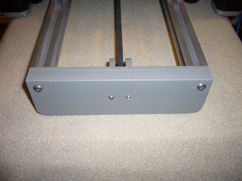
And rear view -
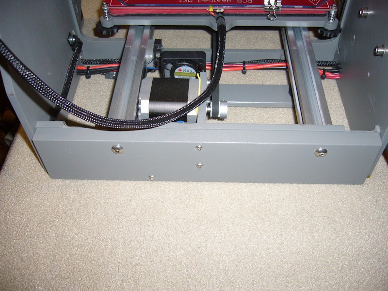
Combined, this made substantial reductions in noise related to Y-axis travel.
FOLLOWUP COMMENT: For those with 10 and 12-inch printers, note that the front and rear frame reinforcement approach was developed on an 8-inch printer. For the larger printers, it may be necessary to replicate any notches in the top of the original rear brace onto the reinforcement so that corner hardware on the Y-bed can clear the rear frame. This wasn't necessary on the 8-inch printer.
Ringing in the helical coil portion of the flexible Z-axis shaft couplers has been eliminated by the dampening effect of a few turns of clear tape added around the coiled part of the couplers.
FOLLOWUP COMMENT: The most significant improvement in noise reduction came later when I adjusted the stepper motor drivers by motor performance, not measured voltage. Set by voltage, I believe the motors are being driven harder than they have to be. Readjusting the drivers so that the motors function without skipping reduces the noise considerably.
OTHER
As of now, I haven't spent the money on the sorbothane feet. I've printed and installed clough42's adapters for them, but just using other adhesive foam I have seems to be working OK with the other reductions I've made. Note that the reinforcement plates added to the front and rear were notched on the bottom to accommodate the round adapters.
FOLLOWUP COMMENT: Sorbothane feet have been purchased and installed.
I've also seen the X belt flapping on the left-side of the X axis v-rails, but only on certain prints. It seems to take a pretty particular combination of carriage position and travel speed to lead to the flap, and it's a pretty low frequency noise. I've added one small piece of Velcro tape to the far-left inside of the v-rail. I don't want to add more throughout the v-rail that might catch on the x-carriage belt mount. In a future mod, I may try adding another of the printed belt guides to a longer bolt on the X-motor eccentric spacer wheel and go from there.
FOLLOWUP COMMENT: I later learned the frequent flapping of the left-side of the X-belt and occasional flapping at the rear of the y-belt could be managed as part of adjusting the stepper motor driver by operational use, not a fixed voltage. I just know the flapping went away when I lowered the drive setting some.Last edited by printbus; 04-30-2016 at 07:12 PM. Reason: clarified how adjusting stepper drivers eliminated belt flapping
-
06-02-2014, 11:59 PM #10Staff Engineer
- Join Date
- May 2014
- Location
- Highlands Ranch, Colorado USA
- Posts
- 1,437
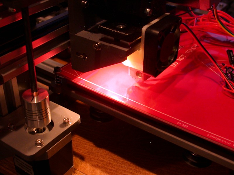
I'm not printing yet, but here's a snapshot showing the illumination from the X carriage LEDs. I wavered between installing three vs six LEDs, but I'm glad I went with six. Three might have been a bit lacking. Originally Posted by gmay3
Last edited by printbus; 05-03-2015 at 06:59 AM. Reason: migrated to offsite image storage due to 3DPrintBoard issues


 Reply With Quote


Please explain to me how to...
05-13-2024, 03:08 PM in 3D Printer Parts, Filament & Materials