


Results 21 to 30 of 255
Hybrid View


-
06-01-2014, 07:08 PM #1Staff Engineer

- Join Date
- Oct 2013
- Location
- Narellan, New South Wales, Australia
- Posts
- 912
Oh! She's completed Phase One of her campaign. Phase Two is when she starts asking why you have to keep spending money on that damned printer. "I thought you said it had everything in it that you needed!" Originally Posted by printbus

OME
-
06-01-2014, 07:34 PM #2Staff Engineer
- Join Date
- May 2014
- Location
- Highlands Ranch, Colorado USA
- Posts
- 1,437

Ha! Yeah, the "didn't it come with what you needed" has already came up. She knows me, though, and all I had to do was say I found a way to improve it and needed to make a run to the local Ace Hardware. To that her response has been "oh, so you're not done Kevinizing it yet". So far, working on the printer has been nothing like the ongoing investment I've had with RC helicopter repairs, but I can see the similarities the future may bring. Originally Posted by old man emu
No build progress today - too much time spent living life.Last edited by printbus; 06-05-2014 at 04:20 PM.
-
06-03-2014, 03:26 AM #3Staff Engineer
- Join Date
- Oct 2013
- Location
- Narellan, New South Wales, Australia
- Posts
- 912
Just a suggestion:
Rotate your RAMPS board 180 degrees. That will give you easier access to the endstop, thermistor and extruder stepper connections. It will also make it easier to access the power and heater (both) connections. It does put the flat cable to the LCD in the way, but that is a small price to pay for better access. I actually attached a plywood plate to the top frame member and have my RAMPS board on top of the printer, to the left of the LCD screen. Really easy access.
Here's how mine looks:
Relocated RAMPS board.jpg
Old Man EmuLast edited by old man emu; 06-03-2014 at 05:47 AM.
-
06-03-2014, 12:53 AM #4Staff Engineer
- Join Date
- May 2014
- Location
- Highlands Ranch, Colorado USA
- Posts
- 1,437
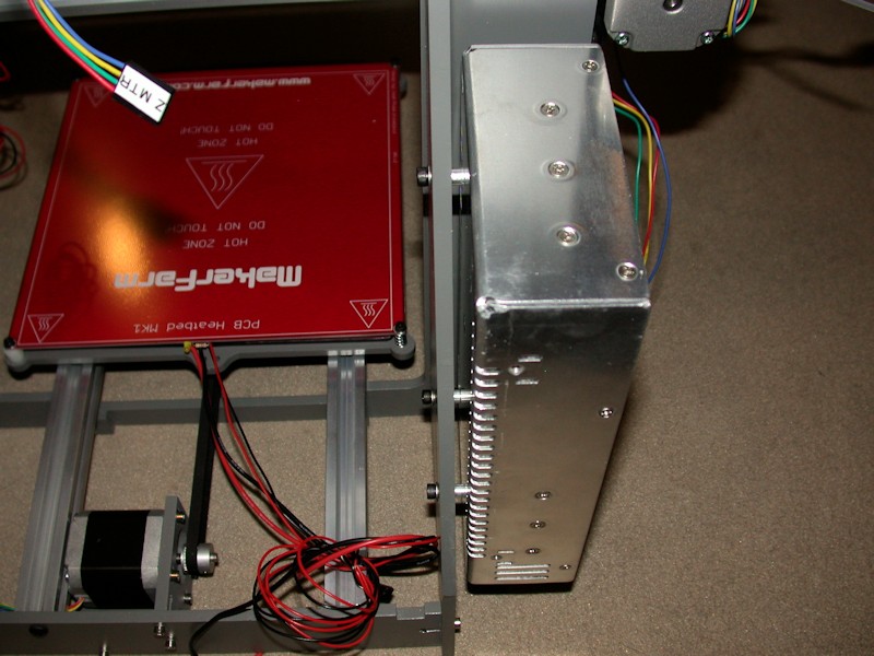
POWER SUPPLY AND RAMPS MOUNTING
I ended up not using the holes MakerFarm provides on the left sidewall for a Mean Well type power supply. I moved the power supply rearward a bit to open up the airflow slots on the forward edge of the power supply, and I moved the power supply upward in order to provide more wiring access room at the power supply terminal block. This does mean, however, that the power supply is now only mounted at three points.
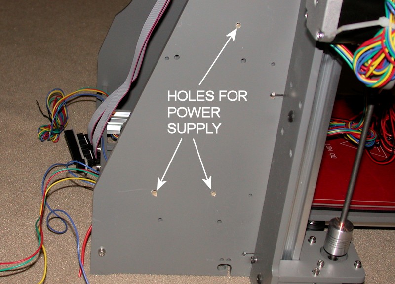
I also used #8 x 1/4-inch aluminum spacers on the power supply in order to open up the airflow slots on the mounting side of the power supply. I'd rather the power supply fan run as little as possible, and I'm hoping these changes improve the cooling obtained just by convection.
The RAMPS and heater relay were mounted in the provided holes. I threw spacers on these too, mainly so I could tuck wires under the boards.
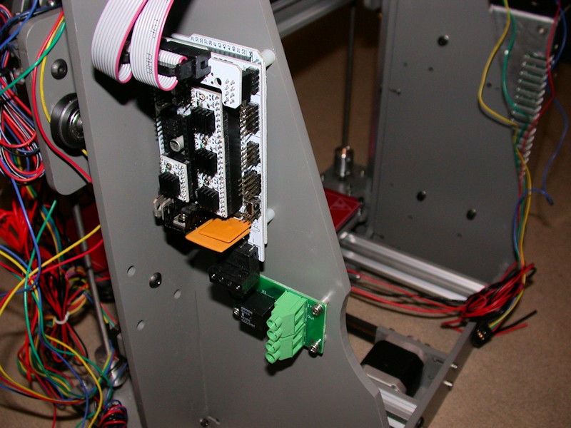
FOLLOWUP COMMENT #1: One of my tougher vibrations to track down turned out to be on the RAMPS board. The two large yellow square components (polyfuses) were touching, and at certain print speeds they'd rattle. To fix that, I added a dab of hot glue between them to ensure the two components aren't touching.
FOLLOWUP COMMENT #2: If you're downloading the Marlin firmware at this point in your build, DO NOT follow the instructions in the build guide RAMPS firmware video on where to get it. I learned the hard way that will get you the firmware intended for the i3, not the i3v. There are some subtle differences in the firmware configuration files. Obtain the files from the RAMPS download link provided in the i3v build guide.Last edited by printbus; 05-03-2015 at 07:03 AM. Reason: migrated to offsite image storage due to 3DPrintBoard issues
-
07-19-2014, 10:54 AM #5Engineer
- Join Date
- Jul 2014
- Location
- Eastern Colorado
- Posts
- 536
Huh, so that's what those holes are for. My heat bed relay melted when I was still using the i3, and I haven't fixed it yet. I've been using the relay mount holes as a place to zip-tie up the cables for the heat bed. Originally Posted by printbus
-
05-30-2014, 01:51 AM #6Staff Engineer
- Join Date
- May 2014
- Location
- Highlands Ranch, Colorado USA
- Posts
- 1,437
Frame and X-axis
FRAME, X-AXIS SUBASSEMBLY, and X-AXIS INSTALLATION
Here I deviate from the sequence of the build guide a bit, deferring the Y Axis subassembly until after the X Axis installation. Since I glued the top plate of the frame on prior to painting, my installation of the vertical rails on the frame has to wait until the completed X axis assembly is ready to install onto the printer.
Be sure to start the X axis installation with the eccentric spacers on the X motor and X idler subassemblies set to provide maximum spacing between wheel rows (i.e., the "loose" orientation). In the build videos, the X axis assembly is slid onto the open top ends of the rails. In my case, I slipped the rails up through the bottom of the Z motor mounts, engaging the T-nuts and wheels in the completed X axis in the process. An advantage of this approach is that the vertical rails can then be pulled flush up to the top frame plate with the bolts used on the extrusion ends.
As with the Y motor, M3 flat washers were added to the M3x12mm bolts used on the X motor mount. M3 x 6mm set screws used on the motor gear instead of the shorter ones included in the kit. Thinking forward to how I plan to do cable and wire routing, I mounted the X motor so that the wires leave the motor on the bottom.
(see the next post for picture)Last edited by printbus; 08-10-2014 at 11:29 PM.
-
05-30-2014, 02:37 AM #7Staff Engineer
- Join Date
- May 2014
- Location
- Highlands Ranch, Colorado USA
- Posts
- 1,437
X Axis alignment
X AXIS ALIGNMENT
While parts of it are, this overall procedure isn't in the build guide. After installation of the X-axis, it occurred to me it would be easy for the X axis to be out of alignment when all the associated hardware was tightened. While manipulating the Z-axis threaded rods can later provide some adjustment to this, I wanted to ensure things were aligned fairly well to start with. Here's what I came up with for an alignment procedure. This sounds complicated, but it really isn't when you're going through the process on the printer.
- Loosen the four bolts at the rear of the X motor and X idler. Following the earlier post, the eccentric spacers for the X motor and X idler should already be in the "loose" position. Now also make sure the eccentric spacer on the X carriage is also in the loose position.
- Verify that the distance between the upright aluminum rails is the same at the top and bottom of the rails. My 6-inch calipers couldn't measure this, but they could measure the gap left after starting with a short metal bar used as a filler. Mine were off a bit and I loosened the bolts on the rails, manipulated them some with a bar clamp, and then retightened the hardware.
- Adjust the eccentric spacer on the X motor (left side) so that all three wheels on the X motor grab the rails. The X motor plate should have little or no play when it is rotated back and forth.
- Now repeat this with the eccentric spacer on the X idler (right side).
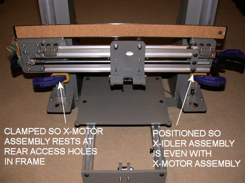
- Add a clamp to the left-side rail and rest the X motor assembly on it so that the four rear bolts on the X motor are accessible through the adjustment holes provided in the frame.
- Now hold a long straight edge (I used an 18-inch metal ruler) on the top edge of the X motor plate so that the straight edge extends to the X idler. Position the X idler so that the top edge of the X idler is also flush with the straight edge. Add a clamp to the right side rail for the X idler to rest on, keeping the X idler lined up with the straight edge.
- Now position the two horizontal rails the way you want them. For appearance, at least line up the ends of the two rails. The rails are a bit short; I positioned mine so there is an equal amount of T-nut exposed on both ends. Then tighten the four rear bolts on both the X motor and X idler. Recheck with straight edge and readjust as necessary. It took me a few tries to get this right, since tightening the hardware will tend to torque the X idler upwards. I ended up putting a bit of downward pressure on the X idler while I was tightening hardware.
- Install and/or tighten the brackets that hold the nuts for the Z axis threaded rods, making sure the X motor and X idler stay resting on the clamps. The nuts and/or threaded rods should not be in place yet.
- With the X carriage at the center of the horizontal rails, adjust the eccentric spacer on the X carriage so that all three wheels on the carriage engage the rails and the X carriage has minimal or no play when it is manipulated. Verify smooth operation of the X carriage across the length of the extrusions. If there are issues in getting a consistent feel (tight on one side, loose on the other, etc.), check for inconsistent spacing between the horizontal rails. Start over at step 1, using a clamp to slightly pull the rails together on the "loose" end.
- Install and/or tighten the X idler pulley bracket so it is vertical. Being exactly vertical isn't critical but why bolt it in place crooked? Watch for any interference with the Z nut bracket on the X idler subassembly. FOLLOWUP EDIT: I later trimmed off the corner edge of the pulley bracket so it doesn't catch on the Z nut bracket.
- Position the gear on the X motor so that the forward edge of the belt is at the forward edge of the horizontal rails. Adjust the belt tension by positioning the X motor in the X motor bracket. I positioned mine to take out any visible sag in the belt and then pulled it just a bit tighter. Tighten the motor mounting screws.
- Tweak how the belt rides on the X idler bearings by adjusting the idler pulley bracket slightly to the left or right. The rear end of the pulley bolt is fixed in the X idler. Moving the pulley bracket to the right (i.e., forward end of the bolt) will cause the belt to move to the rear of the bearings. Moving the bracket to the left will cause the belt to ride forward. Readjust the belt tension if required.
- Remove the clamps from the rails. Verify smooth and consistent Z axis travel. Recheck eccentric spacer settings on the X motor and X idler, and recheck for consistent spacing between the upright rails as required.
Note: Part of what we are hoping for here is perfect parallel alignment between the X carriage and the Y bed without the heater installed. I validated the above straight edge approach using a digital level (RC Logger pitch gauge from my RC helicopter hobby). It shows the difference between the Y bed and the X carriage rails is now within 0.1 or 0.2 degrees.
FOLLOWUP COMMENT: When the four bolts are tightened on the X motor mount and the X idler, you're defining the "natural" position of the idler with respect to the motor. Straightening this out later using the Z threaded rods will add a torque or torsion into the X carriage. It seems to me that if the torsion is high enough, it could help cause the Z motors to skip a step or double step. This is why I wanted to square up the x-carriage before the hardware is tightened.Last edited by printbus; 05-02-2015 at 11:53 PM. Reason: migrated to offsite image storage due to 3DPrintBoard issues
-
01-03-2015, 08:31 PM #8Engineer
- Join Date
- Dec 2014
- Location
- Canada
- Posts
- 498
Your attention to detail is incredible. Im about to start my build, and I hope I can get it atleast half as clean as your build is, well done
-
01-03-2015, 09:09 PM #9Staff Engineer
- Join Date
- May 2014
- Location
- Highlands Ranch, Colorado USA
- Posts
- 1,437
Thanks. Yeah, the detail in the build thread sort of got out of control. My original intent was just to provide some pay back to the 3D PrintBoard community for the few i3v build threads before mine that sold me on the i3v. I seriously believe I couldn't have made a better choice for getting a start in 3D printing. Of course, YMMV. Originally Posted by adamfilip
If you haven't read me harp about it before, I'm all about sharing. The more we all share, the easier it can be for people to pick up on ideas that fit their situation and the better the i3v community becomes. Here and elsewhere, my posts also tend to be verbose so that people have enough background information to make their own decisions.
A challenge in starting a build is in guessing where you want things nice and tidy vs. really want to keep things flexible. While my printer looks quite nice, I admit that can be a hindrance. For example, right now I've got new stepper motors that will require a major effort to install due to the neatly sleeved and tightly routed wire bundles...Last edited by printbus; 01-17-2015 at 07:16 AM.
-
05-30-2014, 02:48 AM #10Staff Engineer
- Join Date
- May 2014
- Location
- Highlands Ranch, Colorado USA
- Posts
- 1,437
Y Axis
Y AXIS
Similar to what I did on the X axis belt, I wrapped the Y axis belt around some aluminum spacers and doubled up on the zip ties. I used 3/8-inch long aluminum spacers, filling the remaining gap in the mounting brackets with two flat washers placed on the side opposite from where the two washers were put on the Y - idler. Washers were put on opposite sides because of the mysterious offset between the brackets on the Y-bed and the brackets on the Y-idler. I ended up with a belt approximately 26-1/4 inches between holes in the two aluminum spacers.
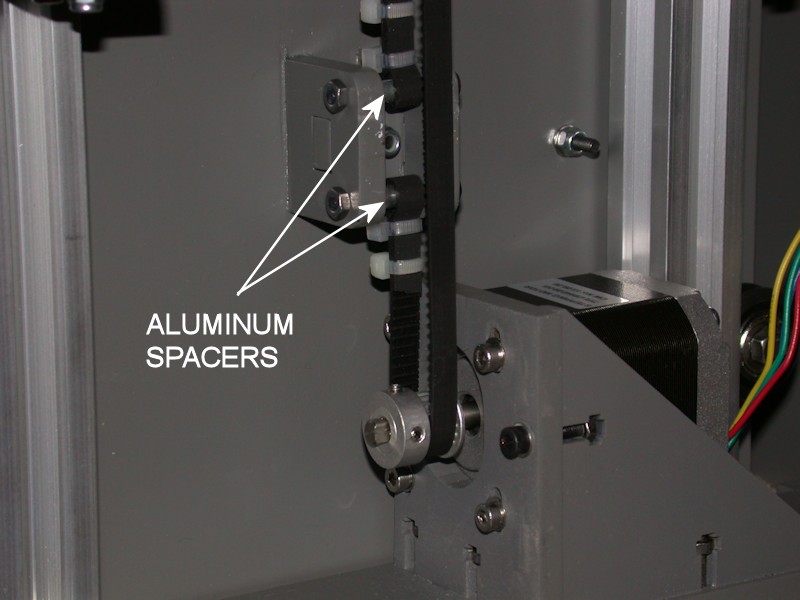
FOLLOWUP COMMENT #1: In adjusting the Y endstop switch, I determined that the uppermost zip tie in the picture had to be moved closer to the aluminum spacer belt mount. As shown here, that zip tie would catch on the bracket holding the Y idler at the front of the printer. I also trimmed back the excess belt to make sure it didn't reach to the bearings in the Y idler. Until the printer was in final assembly, I didn't realize how far forward the Y bed travels.
FOLLOWUP COMMENT #2: The Y axis build video doesn't involve the Y idler in the belt alignment. I suggest first sliding the Y bed forward and adjusting the end loops on the Y bed bracket so they line up with the belt centered on the Y idler. The brackets on the Y bed don't line up well with the brackets on the Y idler, so you'll likely find the belt rides all the way to what will be the right side when the printer is upright. Then slide the bed rearward and adjust the gear on the motor to align with the end loops on the Y bed as done in the video. Slide the Y bed back and forth; try tweaking things if the belt tends to rub on the Y idler brackets.
FOLLOWUP COMMENT #3: Use of an idler pulley on the y-axis idler bearings would obviously help keep the y-belt from rubbing against the idler bracket. My improved version of one is available at http://www.thingiverse.com/thing:790138. My approach to an alternate method of attaching the belt to the y-bed is available at http://www.thingiverse.com/thing:796250.Last edited by printbus; 05-31-2015 at 08:24 AM. Reason: added mention of idler pulley and alternate belt attachment


 Reply With Quote


Please explain to me how to...
Today, 03:08 PM in 3D Printer Parts, Filament & Materials