


Results 11 to 20 of 255
Hybrid View


-
05-31-2014, 02:50 PM #1Staff Engineer

- Join Date
- May 2014
- Location
- Highlands Ranch, Colorado USA
- Posts
- 1,437

Heat Bed Installation
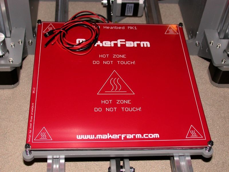
HEAT BED INSTALLATION
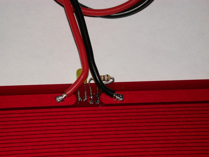
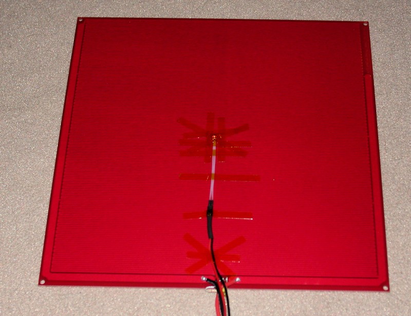
The MK1 heat bed has circuit pads for an LED and current limit resistor(s), and I opted to take advantage of that. The LED will face the rear of the printer, but I like the idea of having a visual indicator that there is in fact power being applied to the heat bed. I didn't have surface mount components on hand, so I tacked on a leaded-type T1 LED and 1K resistor. I also replaced the power wires on the MK1 with 18 gauge flexible silicone wiring. In addition to being very flexible, the high strand count of the wire will hold up better. Another trick from my RC helicopter hobby.
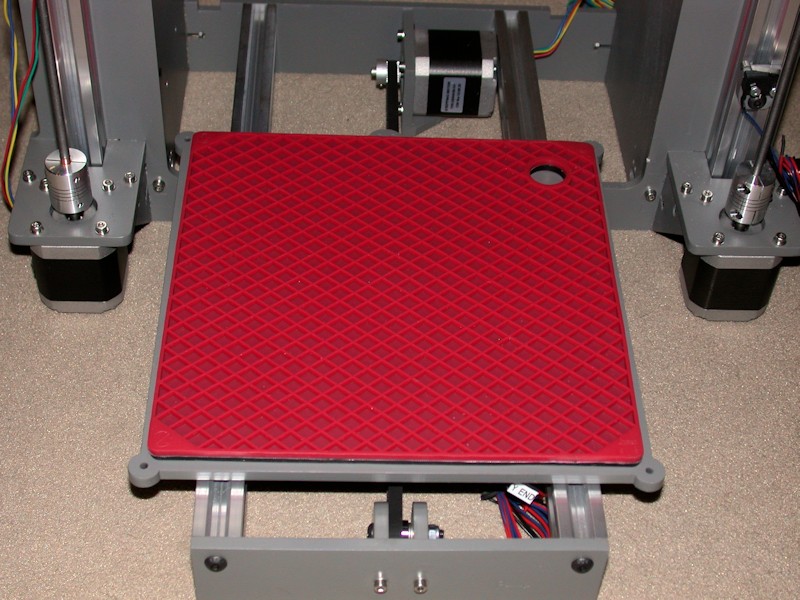
As an insulator between the Y bed and the heat bed, I picked up an 8-inch (200mm) square silicone pot holder/trivet from eBay to try. It's a perfect fit for the heat bed. This has a mesh pattern on both sides, and I trimmed away some of the mesh ribbing on one side to clear the bolt heads on the top of the Y bed. The silicone pad is thicker than what the typical piece of cardboard or cork sheet would be, so I had to increase the nylon spacer in the rear right corner to 3/8-inch. 3/8 of an inch might still be a bit short. I'll convert over to cardboard or cork if I end up needing that printable height loss back at some point.
FOLLOWUP COMMENT #1: In the later post on BED LEVELING, I describe how I revamped the approach to mount the heat bed to the Y bed. All four corners are now equipped with a spring. Longer and fully threaded M3 x 30mm bolts were used and a locknut is used to fix the bolt to the heat bed. Thumbwheels used on the bolts extending through the Y bed to provide a fast, tool-free means of adjustment.
FOLLOWUP COMMENT #2: For a printing surface, I had the local Ace Hardware cut some 1/8-inch glass to 8-3/8 inches square, roughly the same size as the heat bed. They wouldn't cut the angled corners needed to clear the mounting bolts, so I used a wet tile saw with a diamond blade to carefully cut them. I figured if the tile saw can cut glass embedded in mosaic tile, it would likely cut the glass better than I could do with a scribe. A bit of effort with a sanding block softened up the edges around the entire glass plate.
FOLLOWUP COMMENT #3: After using the printer a while, I realized the binder clips used to clamp the glass print surface to the heat bed rub on the heater traces on the bottom side of the heat bed. While I've never heard of anyone reporting wearing through the protection on the heat bed and shorting trace loops with metal binder clips, next time I have the heat bed assembly apart I'm going to add some kapton tape along the bottom sides of the heat bed as an extra precaution.
Last edited by printbus; 05-03-2015 at 07:43 AM. Reason: migrated to offsite image storage due to 3DPrintBoard issues
-
05-30-2014, 01:01 AM #2Staff Engineer
- Join Date
- May 2014
- Location
- Highlands Ranch, Colorado USA
- Posts
- 1,437
Y Bed subassembly
Y BED SUBASSEMBLY
As with other subassemblies, M5 fender washers were used with the eccentric spacers.
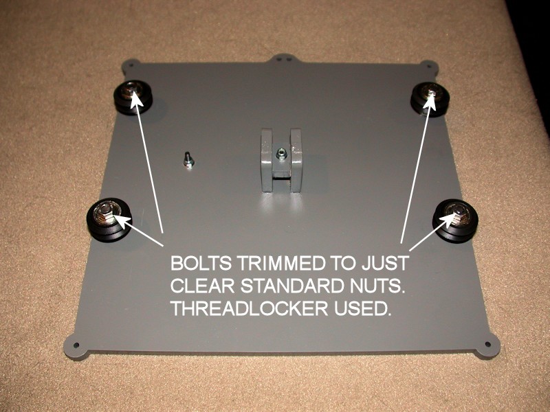
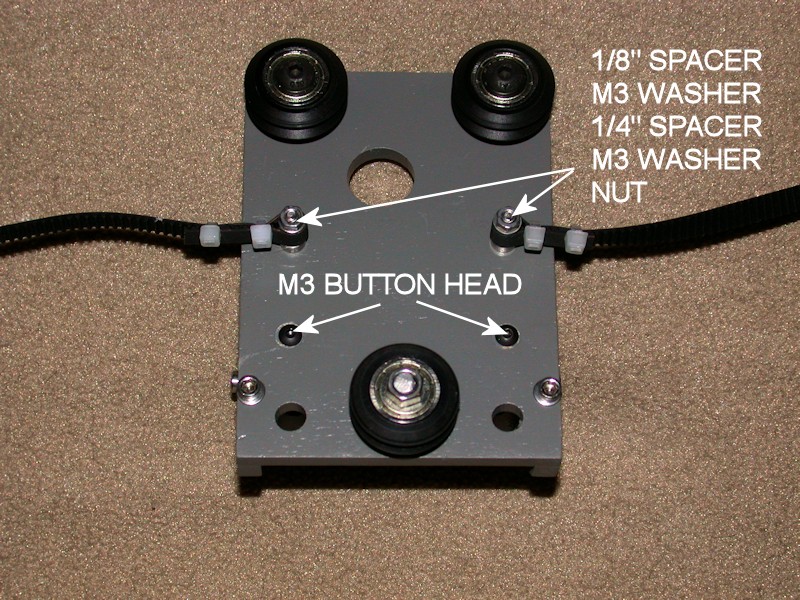
To minimize protrusions on the top side of the Y bed, here I did reverse the wheel mounting bolts so the bolt button heads are on the top side of the bed.
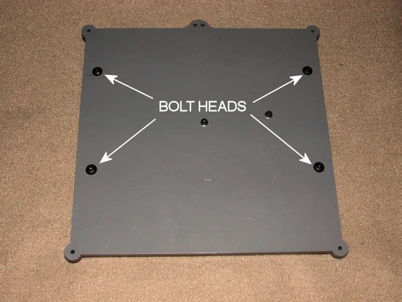
There isn't enough frame clearance on the bottom side for the standard length bolts and the lock nuts, so I used standard nuts and shortened the bolts by about 1.5mm so the threaded end of the bolts are flush with the nuts. Threadlocker was used here in order to keep the nuts tight.
FOLLOWUP COMMENT: I later changed out the M3 bolt that is used with the Y end stop switch for a longer aluminum standoff. See the later ENDSTOP INSTALLATION post for info and a picture.Last edited by printbus; 05-02-2015 at 11:45 PM. Reason: migrated to offsite image storage due to 3DPrintBoard issues
-
05-31-2014, 03:14 PM #3Staff Engineer
- Join Date
- May 2014
- Location
- Highlands Ranch, Colorado USA
- Posts
- 1,437
ENDSTOP INSTALLATION
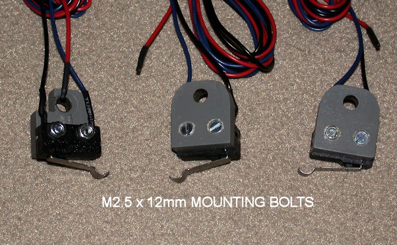
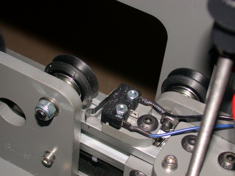
To provide a more permanent endstop setting, I wanted to use bolts and nuts to attach the switches to the endstop brackets instead of zip ties. Holes in the switches are sized for M2.5 hardware. So that the bolt heads wouldn't interfere with the aluminum rails on the back side of the brackets, I used a 3/16-inch drill bit to countersink the M2.5 screw heads. This allows the brackets to mount flush to the rails - another advantage over the zip ties. M2.5 x 12mm screws worked well for mounting the switches. As a good practice, heatshrink was used on the wire connections at the switches. For now, I left the unused red wire in the end stop cables. I assume the RAMPS board puts something like 5V on that wire, which isn't needed in the i3v. Since I plan to sleeve wire bundles wherever I can, I wanted to retain this for future use should I want to upgrade to optical sensors, add lights, etc. Heatshrink was added to cover the ends of the red wire and the wire will be folded over inside the sleeving when I get that far.
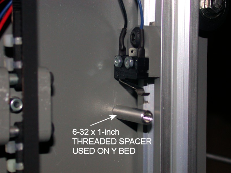
To improve how the Y bed hits the Y endstop switch, the M3 bolt on the Y bed was replaced with a 6-32 bolt and threaded aluminum spacer 1-inch long.
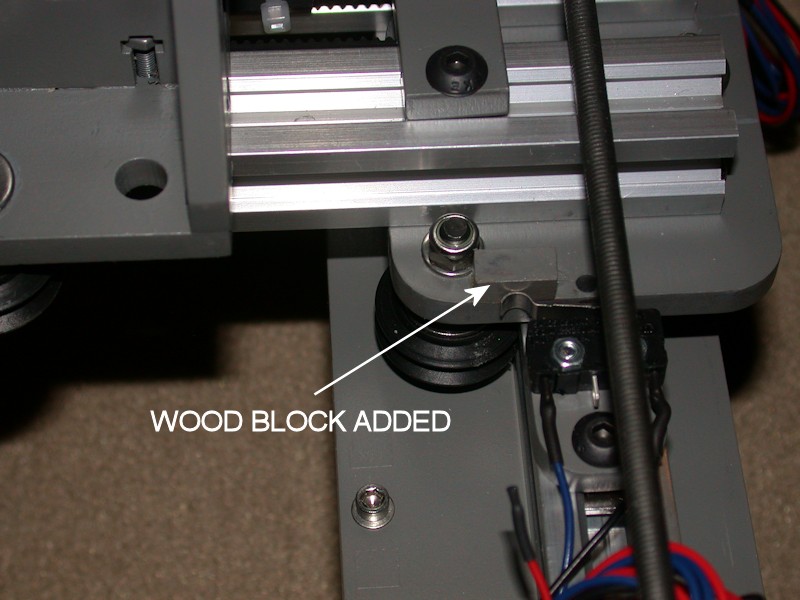
Since I was already weakening the Z-stop bracket slightly by countersinking the bolt heads, I didn't want to shave material off the back side of the mounting bracket as done in the build video. Instead, I glued a small piece of wood scrap from the kit's plywood sheets to the X idler. This gives a good surface area for the Z endstop switch to hit - it's probably a better fix than shaving off the back of the endstop plate anyway. At some point, I may decide to add a similar wood piece to the X carriage for the X end stop.
NOTE: Switch locations in the photos are not final. They'll be adjusted later.
FOLLOWUP COMMENT #1: The unused red wires got pulled out of the connectors for the endstop switches fairly quick. They were just getting in the way.
FOLLOWUP COMMENT #2: In the later WIRE ROUTING (PART 2) post, I relocate the X endstop switch to the bottom of the lower aluminum rail. This requires the switch to mounted on the reverse side of the switch bracket from what is shown in the picture. I also later increased the length of the notch in the switch bracket so that it could slide farther past the nut on the wheel bolt. The small wood block added to the X idler extends farther towards the wheel bolt than it needed to. I got very lucky here. When I moved the X endstop switch to the bottom of the lower extrusion, that small block almost got in the way. I should have kept it shorter.
FOLLOWUP COMMENT #3: Clough42 has several upgrades for the i3v available on Thingiverse, including endstop switch brackets designed to fit the V-groove of the aluminum rail. I found the MakerFarm approach for the Z endstop especially lacking. Clough42 has a great improvement that provides a screw-based Z endstop adjustment. This eliminates the reason for adding the small wood block or shaving off the back of the Z endstop bracket.
FOLLOWUP COMMENT #4: Those clough42 switch brackets only work with the 8-inch printer. There's a similar solution for the 10-inch printer from another user on Thingiverse.Last edited by printbus; 05-03-2015 at 12:14 AM. Reason: migrated to offsite image storage due to 3DPrintBoard issues
-
05-30-2014, 01:23 AM #4Staff Engineer
- Join Date
- May 2014
- Location
- Highlands Ranch, Colorado USA
- Posts
- 1,437
X Carriage Subassembly
X CARRIAGE SUBASSEMBLY
Yeah, another eccentric spacer where I added a fender washer.
Being nitpicky about things, I didn't like how the belt is attached in the build videos. I don't like using multiple nuts on a bolt (can be hard to adjust and keep tight), and I wasn't sure wrapping the belt around an M3 bolt is consistent with the belt minimum bend radius spec. I admit I didn't try to search out what the minimum bend radius is, but I opted to wrap the belt around a 1/4-inch long aluminum spacer. The 1/4-inch length is close to the width of the belt. The stackup of hardware on the bolts is a 1/8-inch spacer, an M3 flat washer, the 1/4-inch spacer, another M3 washer, and a nut. I didn't have enough bolt length for a lock nut, so a standard nut with threadlocker was used instead. For appearance, I reversed the belt mounting bolts so the heads are at the front side of the carriage.
The build guide just says to use a 30 inch length of belt, with determination of the proper overall loop-to-loop length left to the user. I changed mine a few times, and likely ended up with about 28-1/4 inches between the center holes of the spacers on both ends. I doubled up the zip ties partially for appearance but also to help ensure several belt teeth are engaged on each end.
The X carriage is designed so that the heads of the bolts attaching the extruder bracket to the carriage clear the front facing channel of the lower X-axis rail. During my printer final assembly, I was seeing the bolt heads rub against the rail channel. This interference may have went away with final adjustments, but as a precaution I replaced those two bolts with button head types that have a lower profile head.
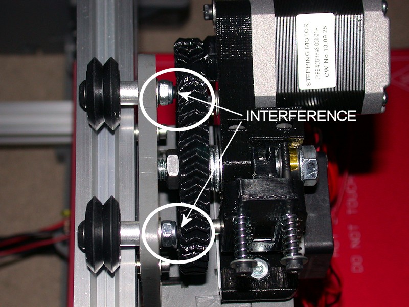
FOLLOWUP COMMENT #1: After mounting the extruder to the X carriage, I noticed the bolts mounting the top wheels were rubbing against the large gear on the extruder. This may have been driven by having to increase the number of spacer washers inside the large gear so the gear would clear the heads of the motor mounting bolts (for the added strength, I used longer bolts with heads and large washers that rest on the far side of the motor mount rather than the typical recessed bolt heads). I ended up shortening those bolts with a file by about 2.5mm so that the ends of the bolts are flush with the locknuts when tightened. See the later EXTRUDER AND HEXAGON HOT END post for a picture showing the interference.
FOLLOWUP COMMENT #2: Limit how much excess belt you have on the side that loops through the X idler, or the excess belt may get drawn into the idler bearings or pulley. Keep that side short, and put the excess belt on the other end.
FOLLOWUP COMMENT #3: During installation of the extruder onto the X carriage, the hot end tip couldn't get any closer than about 6mm inside the 200mm square marking on the heat bed. Part of the solution was to elongate the extruder mounting holes and the large U channel in the bottom of the X carriage to the right so that the extruder can be mounted closer to the X idler side. Next time, I'd elongate them as part of the initial X carriage build.
FOLLOWUP COMMENT #4: There are a few options on Thingiverse for alternate methods of attaching the belt to the x-carriage. My custom belt mount is available at http://www.thingiverse.com/thing:790207Last edited by printbus; 05-31-2015 at 08:16 AM. Reason: Added mention of alternate belt attachment
-
05-31-2014, 03:48 PM #5Staff Engineer
- Join Date
- May 2014
- Location
- Highlands Ranch, Colorado USA
- Posts
- 1,437
Extruder and Hexagon Hot End
EXTRUDER AND HEXAGON HOT END
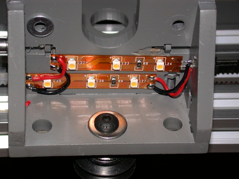
Before I added the extruder assembly to the printer, I opted to add some lighting to the X Carriage. There's a perfect area underneath it for mounting some adhesive strip LED lighting. I used two sections of 12V warm white LED strip lighting that I had leftover from a prior artwork project. A two-pin header was added to the sidewall of the X carriage extruder bracket for use as a connector on the LED wires. I thought about just tying the LEDs into the extruder fan power, but decided to run dedicated lighting wires in case I want to put the LEDs on a switch or dimmer circuit. I plan to sleeve the bundle of wires leading to the extruder assembly, and having a connector on the LED wires will allow me to disconnect the LEDs when I remove the extruder and cable harness from the X carriage for repair or cleaning.
FOLLOWUP COMMENT: A picture showing the heat bed illumination from these LEDs is here.
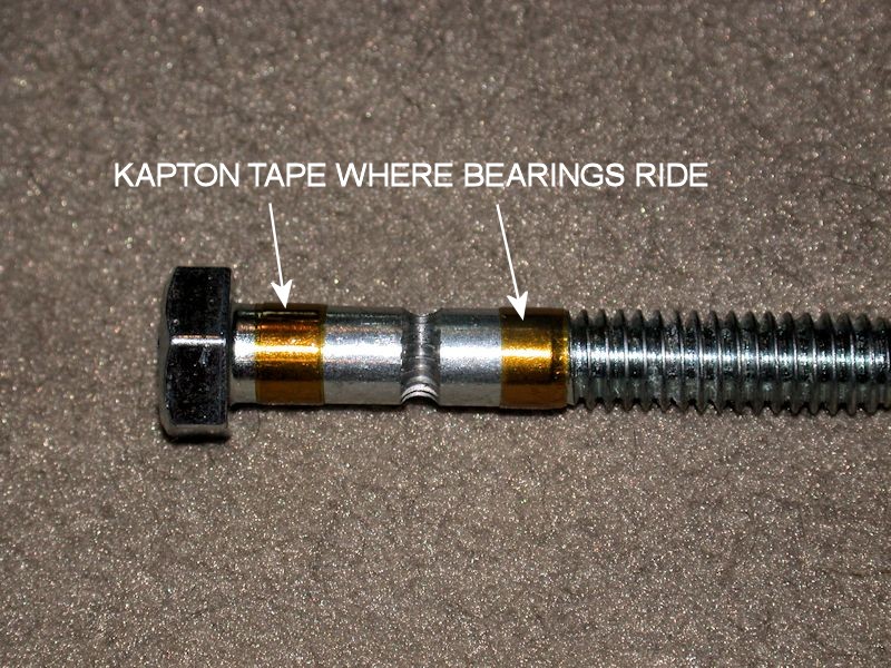
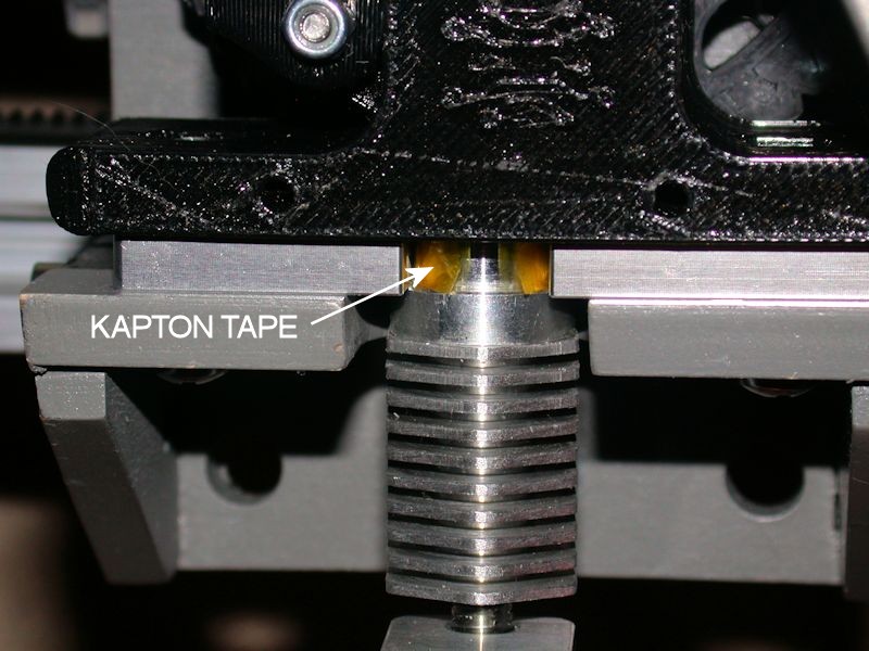
A locknut was used instead of the provided standard nut on the filament release pivot bolt. My printed parts seemed to have a looser fit than those in the build videos. After assembling everything I was disappointed to find a lot of sloppy mechanical play in the extruder tip. Multiple things were done to fix this. To improve how the bearings fit in the extruder, I added a layer or two of kapton tape around them. To minimize slop in how the hobbed bolt fits in the bearings, I added three or four turns of tape to the bolt where the bearings ride. The hex hot end was also a very loose fit in the aluminum mounting plate, so I added a layer of kapton tape to the post of the hex hot end. After final assembly, the extruder tip now has zero play.
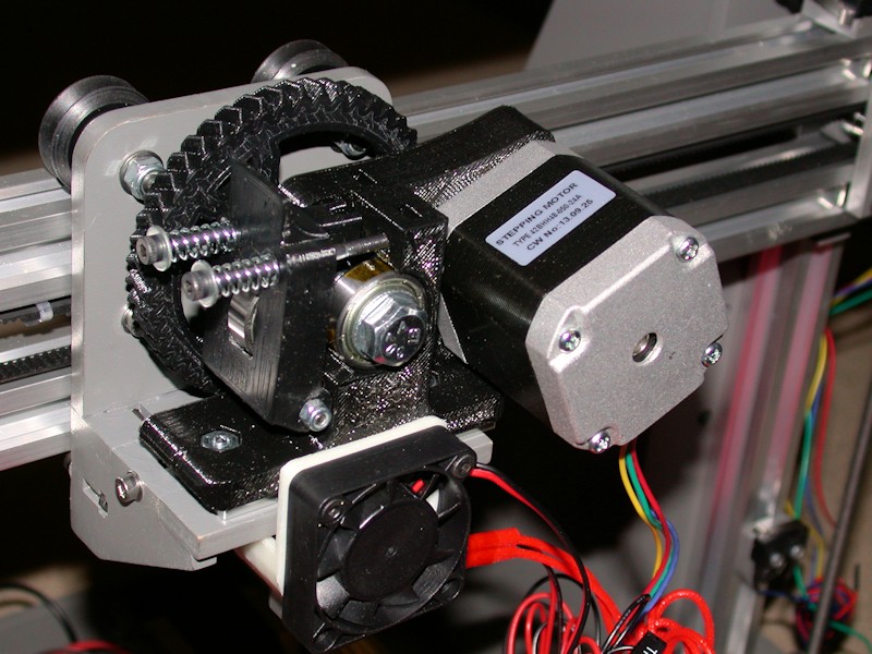
Envisioning how I plan to route wires, I oriented the extruder motor so the wires exit differently than shown in the build video. I found it necessary to lengthen the elongated motor mounting holes in order to obtain good gear mesh, at least with the gears in new and unused condition. M3 x 16mm bolts and M3 fender washers were used on the extruder motor instead of the provided shorter ones that are intended to recess into the wall of the extruder. The face-mounted fender washers should improve the hold as heat from the extruder motor starts to soak through the motor mount. Watch for conflict between the left motor mounting screw and the large gear; use of a button head screw will help reduce the size of the screw head.
The build video discusses the user printing a fan shroud for use with the hexagon hot end. A shroud was included with the hex hot end I ordered with my i3v. I found it challenging to add the shroud and fan on the bench with the hot end and aluminum plate still loose. I ended up mounting the extruder and hot end to the printer and then installing the fan and shroud. I had to enlarge the holes in the shroud for M3 bolts to pass through it.
FOLLOWUP COMMENT #1 - I later realized that since I had added more washers than usual under the large gear to clear my face-tightened motor mounted screws, the large extruder gear was now rubbing against the ends of the bolts for the top two wheels on the X carriage. I ended up fixing this by shortening the bolts with a file so they don't protrude from the lock nuts when they are installed.
FOLLOWUP COMMENT #2 - I applied it later in the assembly, but I followed the ZennmasterM recommendation of using Permatex Muffler & Tailpipe sealer to thermally bond the thermistor to the hexagon hot end. ZennmasterM's use of a syringe would be overkill for the hexagon front end; all I did is dab a bit of it into the dimple provided for the thermistor with a straightened paper clip. After all my wire and cable routing was complete, I redid the kapton tape over the heater and thermistor wires. With wire movement now fairly over, this is when I applied the Permatex sealer.
FOLLOWUP COMMENT #3 - In response to some suggestions I found elsewhere on the web, I've reversed the hot end fan so that it is pulling heat away from the hot end and exhausting it out the front of the printer. This reportedly works better than pushing cool air into the "boxed in" bottom part of the i3v X carriage.
FOLLOWUP COMMENT #4 - The stock shroud for the hex hot end is mounted with the two screws for the hot end cooling fan. The shroud also sort of snaps onto the aluminum barrel of the hot end. I'm not sure what the intent is since that causes the bottom of the shroud to melt where it touches the aluminum block of the hot end. I've subsequently printed the shroud in ABS and cut away the bottom of shroud so it just barely clears the aluminum block of the hot end. This has eliminated the problem with the shroud melting. Having the shroud only supported at the top led to an occasional vibration at some print speeds. This was fixed by adding a silicone isolator between the shroud and the fan.
FOLLOWUP COMMENT #5 - The stock extruder comes with #6 Phillips head screws for mounting to the X-carriage, with nuts that are recessed into the printed extruder base. I replaced the #6 hardware with M4 cap screws, long enough that fender washers and nyloc nuts can be used on the face of the extruder base. I used M4 x 25mm. Cap screws are easier to tighten than Phillips head. Using fender washers on the face provides a lot more surface area that should hold up better to any heat making it's way up from the hot end. Using nyloc nuts should help keep the hardware tight. The screw on the left side can accept a very large washer; I used a 3/16-inch ID washer there that is about 20mm in diameter, just about the same width as the base of the extruder. It's tricky to get the nylock nuts in place, but my hope is that this improved mounting method leads to messing with the mounting hardware less often.
FOLLOWUP COMMENT #6 - Some have had issues with the adhesive backing not holding on similar LED strips. Mine have held fine. I'm not sure if it is the fact that the LED strips I have used 3M branded adhesive or the nature of the painted surface. Adding the kapton tape to the aluminum u-channel has been tricky. In subsequent extruder rebuilds, I've been adding layers of kapton tape as required to the top, round end of the hot end, using the tape as a spacer to push the hot end down into the aluminum bracket.Last edited by printbus; 05-03-2015 at 12:21 AM. Reason: migrated to offsite image storage due to 3DPrintBoard issues
-
10-17-2014, 01:19 PM #6Engineer
- Join Date
- Jul 2014
- Location
- Eastern Colorado
- Posts
- 536
Did you wrap and zip tie the belt around the spacer before or after you mounted the spacers on the bolts in the X carriage? Originally Posted by printbus

-
10-17-2014, 02:03 PM #7Staff Engineer
- Join Date
- May 2014
- Location
- Highlands Ranch, Colorado USA
- Posts
- 1,437
IIRC, I've done both. Sort of. The initial install was done with the X-carriage on the bench and the hardware stackup on the X-carriage. Once I had the X-carriage installed and all the v-rails aligned, I didn't want to take more things apart than I had to in order to adjust the belt length, and I wanted the first zip-tie as snug to the spacer as I could get it. So, to adjust the belt length I loosened the X-motor, marked where the end of the belt flap lined up, took one set of the belt hardware off the X-carriage, re-tied the belt around just the spacer with whatever change in teeth overlap I wanted, reinstalled the hardware on the X-carriage, and repositioned the X-motor. Originally Posted by AbuMaia
I don't recall adjusting the belt length after I had the extruder installed. If I had, I would have probably done as best I could working the belt around the spacer with it still on the X-carriage so I wouldn't have to remove the extruder.Last edited by printbus; 10-17-2014 at 07:16 PM. Reason: added x-motor detail
-
05-30-2014, 01:31 AM #8Staff Engineer
- Join Date
- May 2014
- Location
- Highlands Ranch, Colorado USA
- Posts
- 1,437
Y Motor subassembly
Y MOTOR SUBASSEMBLY
I oriented the motor so that the wires come out of the motor towards the rear. Since I plan to really work cable routing appearance, this should provide the cleanest routing option.
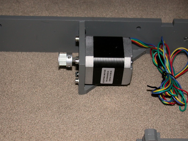
I didn't like the way the set screws provided in the kit ended up being recessed in the pulley threads, so I obtained some M3 x 6mm set screws to use instead. Note that the pulley isn't in the final position on the motor shaft in this picture. M3 flat washers were added to the motor mounting bolts. This takes away from thread engagement in the motor, so I swapped out the 10mm long bolts for 12mm long ones. These are close to bottoming out in the motors, so they're providing as much thread engagement as possible.
FOLLOWUP COMMENT: The natural way to install the motor is to set the motor in the bracket and bolt it in place. I believe one of the sources of vibration I had in the i3v is the bottom side of the Y-motor rattling on the bottom of the motor bracket during certain print moves. I later added some thin silicone sheet material there that helped. Even adding a few layers of high temperature electrical tape might help provide some cushion. The material needs to be very thin or the motor bolt holes won't line up with the holes in the bracket.
FOLLOWUP COMMENT #2: When I later replaced the original CW motors with Kysan motors, the 12 mm screws were too long and I reverted back to 10mm. When the motors were replaced, I added a layer of fiberglass tape to the mounting face of each motor, mainly to keep the motor faces from sticking to the painted surfaces but also to provide at least some vibration isolation.Last edited by printbus; 05-02-2015 at 11:51 PM. Reason: migrated to offsite image storage due to 3DPrintBoard issues
-
06-01-2014, 02:45 AM #9Staff Engineer
- Join Date
- Oct 2013
- Location
- Narellan, New South Wales, Australia
- Posts
- 912
Every time I look at this build thread, I am impressed by the appearance of the printer. It really is competitive with those unbox, plug in, print ones in aesthetic appeal. If it prints like the original i3 it's a real winner.
OME
-
06-01-2014, 09:00 AM #10Staff Engineer
- Join Date
- May 2014
- Location
- Highlands Ranch, Colorado USA
- Posts
- 1,437
Thanks, OME! You're grasping where I'm trying to head with this build. Yeah I've ran into a few minor things, but I'm still pretty happy with the i3v design - I see no reason why it shouldn't be a great printer. I'm futzing around with the build more than I thought I would, but I'm in no hurry. The way I study things tends to drive people around me nuts. I think the kids are glad that they're old enough to have moved away from it. And in this case, the wife has long ago stopped asking if I'm ready to print yet. Originally Posted by old man emu


 Reply With Quote


Ender 3 Neo - Jam Problem
05-08-2024, 03:06 PM in Tips, Tricks and Tech Help