


Results 131 to 140 of 255
Hybrid View


-
12-02-2014, 09:13 AM #1Staff Engineer

- Join Date
- May 2014
- Location
- Highlands Ranch, Colorado USA
- Posts
- 1,437

Here's a link to the slot covers AbuMaia is referring to - http://openbuildspartstore.com/slot-cover-panel-holder/. I used some to form wiring channels in the v-rails, but never got around to installing the decorative ones facing forward.
They do fit in the slots fairly loose and tend to slide around. Use of the M5 bolts and washers on the end of the rails is a good idea - especially for the Z rails. Bending the legs apart on part of the plastic cover may help. I think I pondered using a bit of double sided tape on one end to help hold them in place. The segments I installed with wires and expandable cable wrap are held in place fine by the wiring.
For the bolt heads on the back side of the X carriage shelf, mine were rubbing into the aluminum v-rail so those bolts were replaced with button head type. I had made the problem worse by trying to use flat washers under all the bolt heads, but even without the washers there isn't much clearance there.
FOLLOWUP COMMENT: I haven't verified this, but for those wondering, I don't think you can install the channel cover over slots where the wheels will ride.Last edited by printbus; 12-05-2014 at 03:27 AM. Reason: grammar
-
11-18-2014, 11:11 AM #2Staff Engineer
- Join Date
- May 2014
- Location
- Highlands Ranch, Colorado USA
- Posts
- 1,437
Wow. Over 10,000 thread views. I'm tickled to know people have found the thread informative or at least entertaining. Of course, it does seem like about half of those views might have been myself going back for edits!

Last edited by printbus; 11-18-2014 at 11:30 AM.
-
01-03-2015, 02:32 PM #3Staff Engineer
- Join Date
- May 2014
- Location
- Highlands Ranch, Colorado USA
- Posts
- 1,437
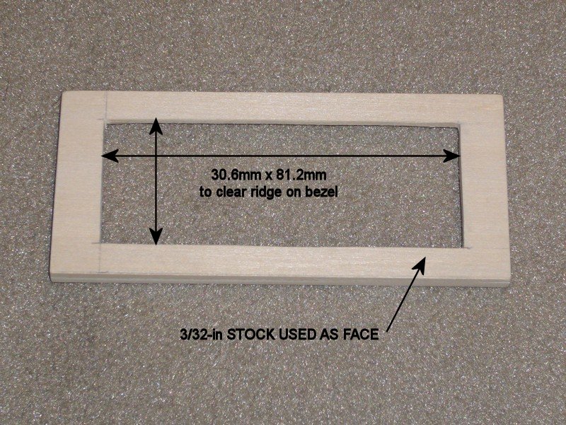
DISPLAY BEZEL
I had to replace the LCD on my i3v due to an inadvertent static discharge that damaged the driver for a column of pixels. It wasn't easy to unsolder the 16 pins between the LCD and the reprapdiscount board, so I wanted to minimize the need to replace the LCD again. I've learned on other projects that using a bezel over one of these LCD modules is helpful in protecting them from static, and obtained another Electronic Assembly EA017-9UKE bezel to use on the printer.
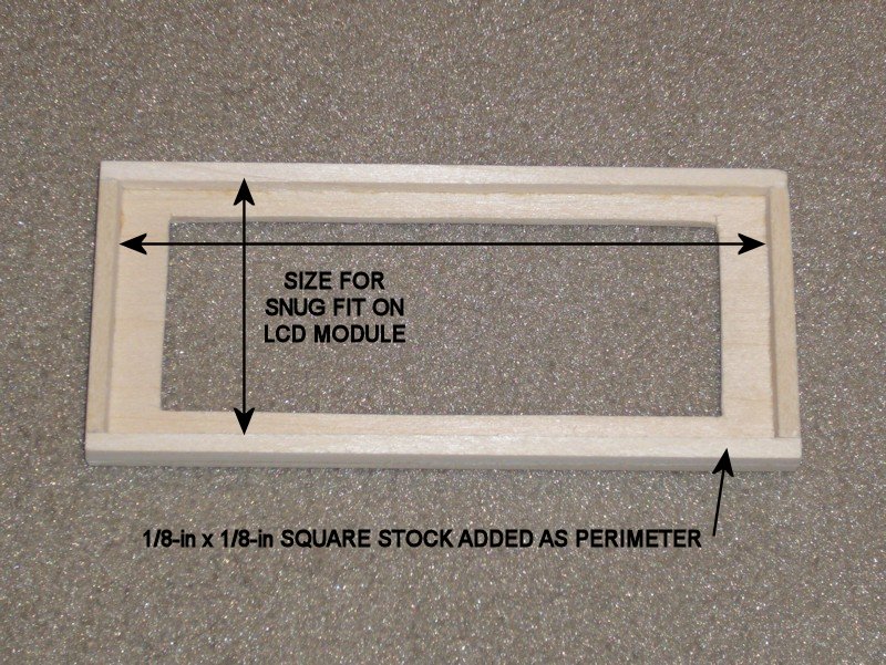
The bezels are meant to mount on a panel, with the display module recessed behind the panel. The design of the i3v printers, however, has the LCD module protruding from the face of the LCD mounting bracket. To provide a mount for the bezel, I used hobby basswood to form a small frame that sits on the LCD module. The bezel frame was fashioned from wood since it was quick and easy to do, and could be painted to have a wood finish like the rest of the printer. I used narrow strips of double-sided tape to attach the bezel to the wood frame, and small dabs of glue to attach the bezel frame to the printer.
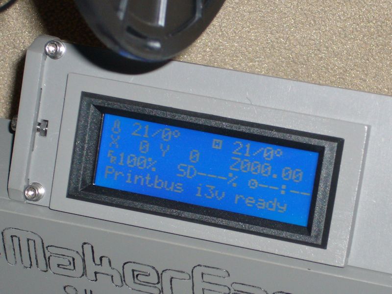
This provides a gap between the anti-glare acrylic glass and the LCD module that should help minimize static being discharged into the LCD.
Last edited by printbus; 05-03-2015 at 03:37 PM. Reason: migrated to offsite image storage due to 3DPrintBoard issues
-
11-13-2014, 12:51 PM #4Technician
- Join Date
- Jul 2014
- Posts
- 64
I am the one with concerns about friction within the spool feed. I am on vacation and can't send photos of my solution, but I used a threaded rod and bearings along with some printed parts to make it work with the spool. I now have a feed that is so smooth it takes almost no effort to turn the spool. I tried the suggested Thingverse part suggested earlier first and found that was not enough.
To be fair, I think that some of my jams were also exacerbated by small parts with frequent retractions. It has become clear to me that it is best to reduce friction in the feed as much as possible. Then consider retraction if there are still jams. Some parts might require alternative settings if retraction will be a problem (no retraction, a little cooler print temp, etc.).
-
12-01-2014, 12:17 PM #5Staff Engineer
- Join Date
- May 2014
- Location
- Highlands Ranch, Colorado USA
- Posts
- 1,437
NOV 2014 BENCHMARKS USING MAKE:2015 TEST MODELS - continued
Results for the Dimensional Accuracy, Overhang Performance, Fine Positive Space Features Performance, and Mechanical Resonance in XY were discussed in the prior post.
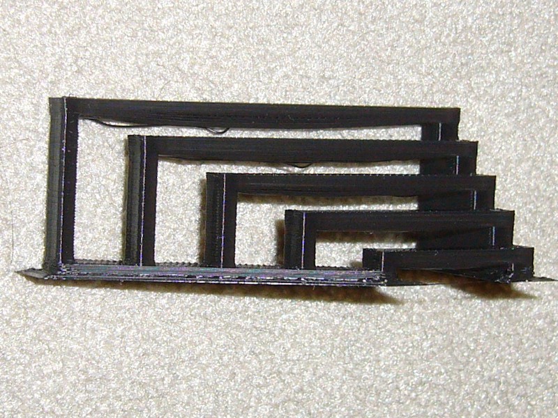
MECHANICAL RESONANCE IN Z
My initial round in ABS didn't fare well, possibly because as the column got taller, I could see the print moving as the nozzle moved around each layer. The final PLA print didn't have that problem and came out very clean throughout the entire column, with no discernible difference between the bottom and top of the column. This was also printed without a minimum layer time constraint, with cooling airflow applied, and zero infill to eliminate bits of infill that analysis in gcode.ws indicated would appear between the inner and outer walls. Scores a 2 out of 2.
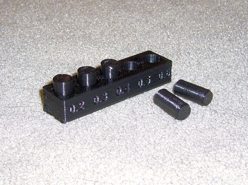
NEGATIVE SPACE TOLERANCES
On the initial ABS print, I could remove three of the pins. On the subsequent PLA print, I could only remove two. Work remains to figure out whether this can be improved through Cura settings. This only scores 2 out of 5.
FOLLOWUP COMMENT: With Slic3r, I obtained a print with one additional peg loose. With Simplify3D, the print had four of the five pins removable.
BRIDGING PERFORMANCE
This model surprised me in both the ABS and PLA prints. I expected very poor results since Cura provides no settings specific to bridging. While there a couple of droopy ones, all spans are intact. The drooping exceeds 2mm, so this gets a 4 out of 5. Not bad for a slicer that most view as incapable of bridging. This model was printed with a brim to ensure bed adhesion. A hefty amount of print cooling airflow was applied, with the print oriented so that the airflow was in-line with the spans.
RESULTS SUMMARY
My assessment of the final prints totals to 24 points out of a possible 29. The biggest hit is the loss of three points since only two pins could be removed in the Negative Space Tolerance test. Not messing around with eliminating the fine strands left on the Fine Positive Space Features Performance test cost a point. And I'm very happy with only losing one point in the Bridging Performance test.
Note that you can't directly compare these totals to the results in the Make: Shoot Out article. Inexplicably, the article uses a different scoring structure than provided in the Thingiverse instructions for the test models. I also wish that Make: would have provided photographs of some of the scoring results in order to improve consistency in the assessment results.Last edited by printbus; 05-02-2015 at 10:43 PM. Reason: migrated to offsite image storage due to 3DPrintBoard issues
-
11-13-2014, 06:09 PM #6Engineer
- Join Date
- Jul 2014
- Location
- Eastern Colorado
- Posts
- 536
I've seen a modified i3v spool holder on thingiverse that is wider, I think to accomodate the wider spools.
-
11-18-2014, 08:02 AM #7Technologist
- Join Date
- Aug 2014
- Location
- Oklahoma
- Posts
- 191

 I will have to to print this one out once I am printing, thanks AbuMaia!
 Originally Posted by AbuMaia

On another note, since I hot my heat bed heating issues fixed (see the heatbed heating thread), I attempted to print the test cube. I found that the extruder is not feeding into the hotend. I am going to take it apart, but from the looks of this picture, it might just be an alignment issue. As the extrude wanted to push the filiment down, and the retract would pull it out just fine. Any other thoughts? It is hard to tell but could I just tighten the hobbed bolt more to get it to move in further?extruder.jpg
-
11-18-2014, 08:15 AM #8Engineer-in-Training
- Join Date
- Mar 2014
- Location
- USA
- Posts
- 388
Without having my own printer in front of me for reference, it seems like the bearing in the front is seated correctly, meaning it appears to be tightened all the way. Could the guidler somehow be misaligned?
-
11-18-2014, 09:23 AM #9Staff Engineer
- Join Date
- May 2014
- Location
- Highlands Ranch, Colorado USA
- Posts
- 1,437
Something's not right there. Duh. Comparing to my printer, your bearing does appear to be fully seated, and the left side of my guidler rides against the extruder body just like yours is. If you take things apart, you could see if the hole for the bearing needs to be cleaned out some, and you could try a thinner washer under the head of the hobbed bolt. I doubt that'd fix the misalignment you have though. Have you tried talking to Colin about it, perhaps sending him the picture or linking to here? Maybe they end up with a bad hobbed bolt every now and then. Originally Posted by usarmyaircav
EDIT: And looking at my printer for this I now see the kapton tape I had wrapped around the hobbed bolt to improve the fit in the bearings has crept into the cut area of the hobbed bolt for some reason. I wonder how long ago that happened.Last edited by printbus; 11-18-2014 at 09:42 AM.
-
11-18-2014, 09:36 AM #10Technologist
- Join Date
- Aug 2014
- Location
- Oklahoma
- Posts
- 191
Thanks Kevin, I will send that to him. Great idea. I just sent him pictures of my spool holder, as I asked him about it since the spool won't rotate without me manually rotating it. Originally Posted by printbus


 Reply With Quote


Ender 3 Neo - Jam Problem
05-08-2024, 03:06 PM in Tips, Tricks and Tech Help