


Results 1 to 10 of 255
Hybrid View


-
06-01-2014, 07:08 PM #1Staff Engineer

- Join Date
- Oct 2013
- Location
- Narellan, New South Wales, Australia
- Posts
- 912
Oh! She's completed Phase One of her campaign. Phase Two is when she starts asking why you have to keep spending money on that damned printer. "I thought you said it had everything in it that you needed!" Originally Posted by printbus

OME
-
06-01-2014, 07:34 PM #2Staff Engineer
- Join Date
- May 2014
- Location
- Highlands Ranch, Colorado USA
- Posts
- 1,437

Ha! Yeah, the "didn't it come with what you needed" has already came up. She knows me, though, and all I had to do was say I found a way to improve it and needed to make a run to the local Ace Hardware. To that her response has been "oh, so you're not done Kevinizing it yet". So far, working on the printer has been nothing like the ongoing investment I've had with RC helicopter repairs, but I can see the similarities the future may bring. Originally Posted by old man emu
No build progress today - too much time spent living life.Last edited by printbus; 06-05-2014 at 04:20 PM.
-
06-03-2014, 06:22 AM #3Staff Engineer
- Join Date
- Oct 2013
- Location
- Narellan, New South Wales, Australia
- Posts
- 912
LED Illumination
Here are some pix to show how my 3 x LED light strips illuminate the print area.
Here is the print area with the lights off:
Lights Off.jpg
and with the lights on (no flash for photo)
Lights On.JPG
Here's how it looks in photos taken with a flash.
Lights off
Lights Off - flashlit.jpg
Lights on
Lights On - flashlit.jpg
Here's the link to how I did it: http://3dprintboard.com/showthread.p...the-Print-Area
Old Man EmuLast edited by old man emu; 06-03-2014 at 07:13 PM.
-
06-03-2014, 07:23 AM #4Super Moderator
- Join Date
- Apr 2014
- Location
- Lone Star State
- Posts
- 2,182
I have a couple of LED's embedded into my extruder to do the same thing. But they burned out. They still light up but are not bright enough to serve any purpose now. I like the light strip idea. I think I'll go scrounge on eBay and see if I can find something suitable for my setup!
-
06-08-2014, 09:00 AM #5Staff Engineer
- Join Date
- May 2014
- Location
- Highlands Ranch, Colorado USA
- Posts
- 1,437
BED LEVELING
The bed leveling concept for the i3v seemed pretty straightforward. Adjust the Z endstop for the desired hot end clearance over the fixed-height home corner of the bed, and then adjust the other three corners to match the clearance. Yeah, right. I found it impossible to adjust the Z endstop with any accuracy or repeatability, especially since even a slight change in the angle of the switch makes a big difference when you're adjusting to paper thickness clearance. When I lucked into a Z endstop position that might work, adjusting the other three corners was tedious, having to repeatedly move the bed and then switch between adjusting the height and checking clearance.
Rather than revamp the Z endstop design, here's what I implemented to provide an easier adjustment. The Z endstop will be left at a fixed height. All four corners of the heatbed are now adjustable; I found a spring somewhat like the other three to use on the home corner and removed the spacer. M3 x 30 bolts now used in each corner, with a locknut installed to fix the bolt to the heat bed so it won't rotate. Springs between the locknuts and the Y bed. The springs Makerfarm provided in the kit slip perfectly over the round end of the M3 locknuts. M3 wing nuts or thumbwheels under the Y bed for adjustment. Z endstop switch set generally where it should be for the spacer height that used to be in the home corner, and will no longer be adjusted.
Tired of spending money at the hardware store for this thing, I thought I'd try printing some M3 thumbwheels to use under the Y bed. I was surprised to no end when the first print I've ever done came out usable, especially with the Z axis stepper motor running with an indeterminate current limit setting because of the damaged driver board.
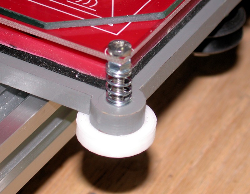
After adopting this approach, adjusting the bed for proper clearance in all four corners is trivial, and requires no tools. It took just a minute or two to tweak thumbwheels using a piece of paper for a gauge before subsequently printing my LCD knob. The surface area between the Y bed and the thumbwheels seems very adequate for keeping the thumbwheels in position.
I'm sure the concept of the thumbwheels isn't new, but I have no idea who to give credit to.
FOLLOWUP COMMENT: BTW, my bed leveling process starts with using the long straightedge to check for proper adjustment between the X motor plate and the X idler plate like I did during the X axis alignment. Z rods rotated as necessary to get them aligned with each other. I figure any mismatch from how I aligned them previously will lead to some torsion in the X axis, possibly increasing the chance of a Z motor skipping a step or doublestepping.
FOLLOWUP COMMENT #2: The design of the first M3 thumbwheels used includes a fine ridge for grip that didn't come out on my print. When I wanted to reprint the thumbwheels in black, I went for a different design with more a pronounced finger grip although I did have to file down the ridges a bit on the left rear position to clear the frame.
FOLLOWUP COMMENT #3: The Z endstop switch implementation was later revamped to a screw-adjustable design. That's a far better implementation.
FOLLOWUP COMMENT #4: The original post mentioned M3 x 30mm bolts being used in each corner. I think they are actually M3 x 25mm.
FOLLOWUP COMMENT #5: I later realized a significant advantage to the different design thumbwheels installed later. That design has 10 ridges around the circumference of the thumbwheel. With the 0.5mm pitch for the M3 hardware, this equates to 0.05mm in height adjustment for each ridge. In switching between printing directly on glass and then printing on painters tape, I can get very close to an initial adjustment by just rotating each thumbwheel by two notches to adjust the bed 0.1mm in height.
FOLLOWUP COMMENT #6: For those with 10 and 12-inch printers, note that the thumbwheel approach here is implemented on an 8-inch printer. For the larger printers to get the extruder to the front of the print bed, the rear of the Y-bed will need to extend beyond the rear frame brace that goes across the back of the printer. That rear frame brace may need to be modified to provide the additional clearance needed for the thumbwheels and/or the bolts used in the two rear corners.Last edited by printbus; 05-03-2015 at 07:20 AM. Reason: migrated to offsite image storage due to 3DPrintBoard issues
-
06-06-2014, 10:05 AM #6Staff Engineer
- Join Date
- May 2014
- Location
- Highlands Ranch, Colorado USA
- Posts
- 1,437
MOTOR TESTING AND ENDSTOP ADJUSTMENT
It was great to finally be controlling the motors from the LCD. In my case, I had to reverse the plugs for both the X motor and the Y motor at the RAMPS board to get the proper movement directions. No issues surfaced in adjusting a general placement of the Z endstop switch.
Some may recall I put two zip ties on each of the belt ends. On the leg of the Y belt that loops forward through the Y idler, I had to move the forward zip tie closer to the belt mounting bolt, since it was tending to catch on one of the idler pulley brackets when the bed was fully extended. I also trimmed off some of the excess belt so it wouldn't encroach on the idler bearings. After that, I could position the Y endstop switch so the home position of the hot end is at the rear marking of the square on the heat bed.
Adjustment of the X home position wasn't as easy. With the endstop switch as far right as it would go, the hot end tip was still about 6mm inside the marking on the heat bed. I can't imagine ever printing anything that actually needs the full 200mm capability, but I took on achieving it as a challenge. Several tweaks were involved, with each providing just a portion of the correction.
- Using a round needle file, I elongated the extruder mounting holes in the X carriage to allow the extruder to slide to the right maybe 1.5 or 2mm. For good measure, I enlarged the large U-shaped channel for the hot end an equal amount. I probably could have elongated the holes a bit more, but at some point the head of the right-side extruder mounting bolt will be up against the carriage sidewall and limit how far the extruder can slide over.
- Having previously relocated the X endstop switch to the bottom X axis aluminum rail turned out to helpful. On the upper location, the range of adjustment of the X endstop switch is limited by the Z nut bracket on the X idler. The bottom side doesn't have that problem. I cut out 1.5 or 2mm of additional wood from the notch in the X endstop bracket so it could pass farther over the nut for the lower X idler wheel bolt.
- Although the notch clears the locknut, now the wide button head screw mounting the X endstop was binding up on the bolt protruding from the wheel bolt locknut. Shortening the bolt would have required some serious disassembly, so I swapped the button head on the endstop bracket with a normal cap screw which has a slightly narrower head.
- Using a needlenose pliers, I "flattened" most of the U-hook out of the endstop switch lever so the X carriage travels farther before the switch activates.
- Finally, I angled the endstop bracket on the extrusion just a bit to rotate the end of the switch lever away from the X carriage.
I wanted to measure and record the baseline current limit settings for the stepper motor drivers. That led me to realize the trimpot on the Z driver was broken and the entire top half with the wiper was gone. I appeared to be driving the motors OK, but I'm not sure how the A4988 chip deals with the now unconnected current limit input signal. I'm limiting what I do with the printer until I get the replacement driver. The top part of the trimpot was later found in the bubble package from the RAMPS board.
FOLLOWUP COMMENT: The Pololu Black stepper driver I purchased got here before the MakerFarm replacement, so I've installed the Pololu.Last edited by printbus; 08-10-2014 at 11:50 PM.
-
06-03-2014, 03:26 AM #7Staff Engineer
- Join Date
- Oct 2013
- Location
- Narellan, New South Wales, Australia
- Posts
- 912
Just a suggestion:
Rotate your RAMPS board 180 degrees. That will give you easier access to the endstop, thermistor and extruder stepper connections. It will also make it easier to access the power and heater (both) connections. It does put the flat cable to the LCD in the way, but that is a small price to pay for better access. I actually attached a plywood plate to the top frame member and have my RAMPS board on top of the printer, to the left of the LCD screen. Really easy access.
Here's how mine looks:
Relocated RAMPS board.jpg
Old Man EmuLast edited by old man emu; 06-03-2014 at 05:47 AM.


 Reply With Quote


Ender 3 Neo - Jam Problem
05-08-2024, 03:06 PM in Tips, Tricks and Tech Help