


Results 1 to 10 of 255
Hybrid View


-
05-26-2014, 08:59 PM #1Staff Engineer

- Join Date
- May 2014
- Location
- Highlands Ranch, Colorado USA
- Posts
- 1,437

General observations
UPGRADES TO WOOD FRAME COMPONENTS
Now that the i3v has been out for a while, upgrades and modifications for it are available on Thingiverse. Those about to assemble the i3v are encouraged to search Thingiverse using search terms such as MakerFarm or i3v. While it may not be possible for some to print parts until they get a printer working, it might be good to know ahead of time where later upgrades may be retrofitted.
BUILD GUIDE
The MakerFarm build guide and videos are OK, but not perfect. I printed a copy of the build manual so I had a place to capture notes as I go. I suggest those building the printer skim through all the videos before doing anything. One video cuts off at the end but the missing effort is described in a subsequent video. There are a couple of places where things are put together wrong and corrected in the next video. The printed copy is good for noting things like this. I also archived copies of the build videos.
There is one definite correction to the build guide as it was in April 2014. The page titled "Adjusting the Stepper Drivers" says you should select the DC Current mode on your multimeter. Doing so will short out the voltage points being probed here - a bad thing to do. You need to select DC Voltage mode on the multimeter, as the multimeter picture on that page does show. (NOTE: This error has been corrected this in updated versions of the build guide.)
UNPACKING AND HARDWARE NOTES
Extruder parts are conveniently packaged separately from the rest of the printer. Except for a few bolts in the extruder package, all screws in my kit were black. Washers and nuts were steel colored - not black.
Contrary to the videos, the delrin wheels now come with bearings preinstalled and each wheel wrapped in plastic. A proper shim washer is included between bearings in all of the wheels. The shim will minimize issues in how tightly the wheels are bolted on. I had purchased 1mm shims to use for this since the videos only addressed using a washer as a shim on just a couple of the wheels; oh well.
For anyone interested in the detail, the aluminum v-rails in the 8-inch i3v are 375mm long. The 5mm threaded rods are 330mm long. Motor shafts are 5mm diameter and include flats. The shaft on the LCD rotary encoder is 6mm diameter and also is flatted on the end, although the lower part of the shaft is round.
At a minimum, tools required for the 3mm cap screws and 5mm button head screws will include 2.5mm and 3mm hex drivers or allen keys, as well as 5.5mm and 12mm sockets or wrenches. Having an assortment of good hex drivers would be handy. A 3mm T-handle hex driver was later found to be very helpful for some of the M5 screw locations.
I feel the M3 x 4mm set screws included for the two motor pulleys are pretty short - they'll recess well into the gears when tightened. I purchased some 6mm long set screws off eBay.
I'm adding flat washers to many screws, especially those on the motors. I'm going to increase the length of the motor mount screws to 12mm to ensure maximum thread engagement in the motors. I also obtained larger diameter fender washers to use with the eccentric spacers.
The left sidewall of the frame comes predrilled with two sets of power supply mounting holes. One set of holes fits the common Mean Well type 12V 24A and 12V 30A supplies. Those wanting to mount a Mean Well or knock-off power supply to the provided holes in the left sidewall will need to obtain some M4x8 or M4x10mm screws.
The laser cut edges of the veneered panels have a glazed finish. Those wanting to paint or glue will likely want to sand the glazing for better adhesion.
My kit came with a 4GB SD card, a 1.8m/6 ft shielded USB cable, and an extra fan that could possibly be used as a print cooler. The wire packet comes with a number of extra thermistor and motor wires with header connectors already installed on one end.
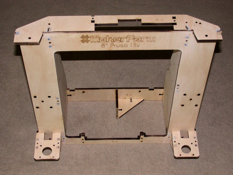
INITIAL ASSEMBLY OF THE WOOD COMPONENTS
The initial round of assembly efforts were focused on getting the wood parts painted so they could thoroughly dry while I was on travel for a while. Where wood components are fastened without adjustment or obvious need for future disassembly, I glued the wood joints. This should ensure long term rigidity to the frame. Screws and other hardware like idler bearings were installed for the glue-up. I just used normal wood glue.
I wasn't overly impressed with the fit of the belt mount brackets on the Y-bed, and added some shim stock to ensure a better fit. Clamps were used to ensure perpendicular joints here and on the front Y-idler bracket came out 90 degrees. I should also point out that the two pairs of stubs on the cross piece for the Y-bed mount aren't the same exact dimensions. I oriented the cross piece to provide the squarest overall fit with the holes of the Y-bed.
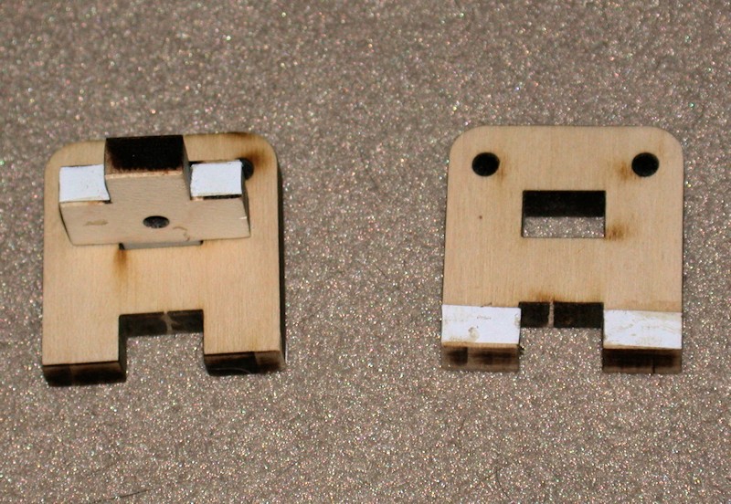
The post and slot joints were filled with Minwax epoxy wood filler and sanded so they won't be visible after painting.
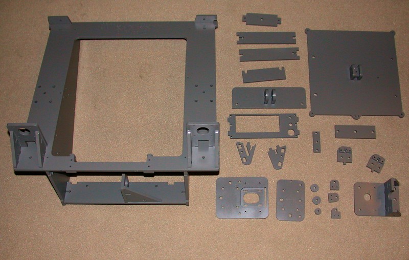
After the glue had set, screws and other temporarily installed hardware were removed prior to painting. The LCD assembly and spool holder were not glued before painting. I opted for a satin dark gray color (RustOleum Granite) spray paint to complement the décor of my combination home office/workshop and as what seems like a good mix between the aluminum and black components on the printer. The expandable cable sleeving I'll be using throughout will also black.
FOLLOWUP COMMENT #1: During final assembly, I opted to add some LED strip lighting to the underside of the X carriage. If I had known that when I was painting, I may have painted the underside white rather than gray just because white would have reflected light better than gray.
FOLLOWUP COMMENT #2: If I could do it over again, I would not have glued up the x-carriage before painting. Keeping the parts separable may be helpful if future mods include replacements to bracket components, for example.
GENERAL ASSEMBLY COMMENTS
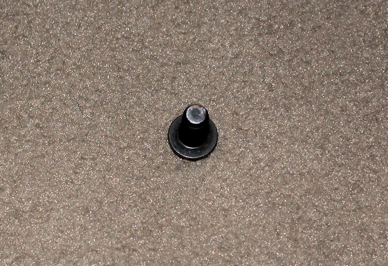
In fit checks and initial assembly efforts, I've noticed many of the M5x12mm bolts fastening things to the v-rails are cutting rings into the bottom of the extrusion channels when the bolts are tightened. The screws should be pulling the nut plates against the top edge of the extrusion without bottoming out in the channels. The fact that they're starting to engage with the bottom of the extrusion channel means the bolts may not be properly gripping whatever is being clamped to the v-rail. Screws tend to have a raised rim on the end from the manufacturing process, and these bolts are no different. While the bolts may work OK as is with the extrusion engagement, I opted to file away at least the raised rim on the bolt ends.
FOLLOWUP COMMENT: There are several places where I mention shortening bolts with a file. In ALL cases this was done with the bolt removed from the printer so that filings were kept away from bearings, the aluminum rails, electronics, etc. I also had been planning to use threadlocker on all metal-to-metal fasteners where nyloc nuts aren't or can't be used. I'm having to rethink this since a lot of the hardware is temporarily installed and readjusted later in the assembly.Last edited by printbus; 05-31-2015 at 08:04 AM. Reason: migrated to offsite image storage due to 3DPrintBoard issues
-
05-30-2014, 02:53 AM #2Staff Engineer
- Join Date
- May 2014
- Location
- Highlands Ranch, Colorado USA
- Posts
- 1,437
LCD assembly and installation
LCD INTERFACE and LCD INSTALLATION
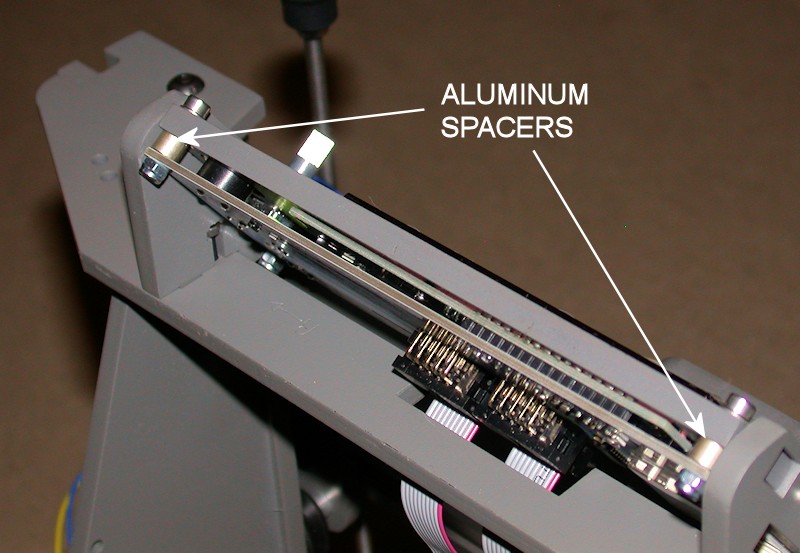
I didn't like the way the build videos clamp down on the display board and bend it. To prevent this from happening, I used some 3/16-inch long spacers between the display board and the LCD bracket. The spacers really can't be any longer than this or the LCD bracket end will start to interfere with the SD card slot.
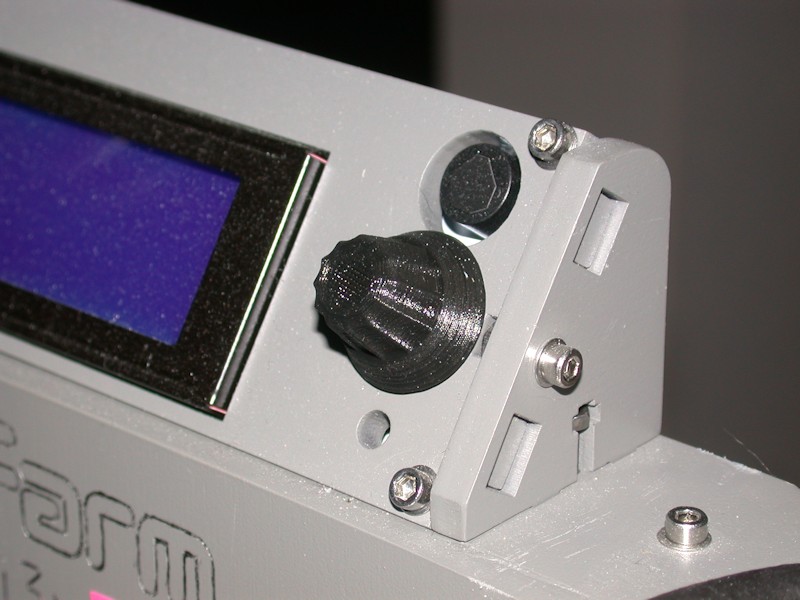
FOLLOWUP COMMENT #1: I've had several cases where the display either blanks out or displays random garbage after I first touch the encoder shaft or the metal knob I had installed on the shaft. There might be a static discharge issue here, so I replaced the metal knob with a printed knob to see whether the problem goes away with an insulated one. A better knob was later found on Thingiverse and used instead.
FOLLOWUP COMMENT #2: The buzzer on the LCD is quite loud. I tamed mine down by covering the hole in the front of the buzzer with a small piece of black electrical tape.
FOLLOWUP COMMENT #3: The display comes preassembled with one row of soldered pins fastening the two boards together. At some print speeds, I've had the LCD board vibrate against the larger board and/or vibrate against the wood frame. To fix this, I added a few dabs of hot glue between the two boards, opposite from the row of soldered pins. Double-sided foam tape or something similar could also be used to improve how the two boards are fastened together.
FOLLOWUP COMMENT #4: There were additional rattles coming from the LCD vibrating in the wood frame. Narrow strips of electrical tape were added as a cushion to either the wood, the circuit boards, or the metal frame on the LCD so that no two hard surfaces can vibrate.Last edited by printbus; 05-03-2015 at 12:00 AM. Reason: migrated to offsite image storage due to 3DPrintBoard issues


 Reply With Quote


Please explain to me how to...
Today, 12:15 PM in 3D Printer Parts, Filament & Materials