


Results 1 to 10 of 255
Hybrid View


-
02-03-2019, 11:21 AM #1Staff Engineer

- Join Date
- May 2014
- Location
- Highlands Ranch, Colorado USA
- Posts
- 1,437

Z-AXIS LEAD SCREW UPGRADE
I was never thrilled with the 5mm threaded rods MakerFarm used for the Z-axis. They worked, but were so S-L-O-W. As a result of testing for an upper limit, I ran a z-axis feed rate of 2.5mm/Sec. A full 200mm of z-axis travel would mean 80 seconds of travel time.
From what I recall back in the i3v heyday, lead-screw upgrades always involved new Z-axis motor mounts that moved the motors farther from the frame. Since I overachieved and glued together all the fixed joints in the i3v wood frame during my initial assembly, swapping out the Z-axis motor mounts would not have been an easy thing to do. So, I just put up with the slow feed rate of the 5mm rods.
In a recent scan of i3v stuff on Thingiverse, I realized there were options for lead screw upgrades that retained the original motor mounts. With the right style of nut on the lead screws, new Z-axis nut plates is all that would be required. The i3v Lead Screw Nut Plate by cperiod even provided openSCAD source, so I went for it. I used 8mm diameter, 400mm long 4-start (8mm travel per turn) lead screws and brass nuts from ZYLTECH, along with their 5mm to 8mm shaft adapters. I debated whether single-start (2mm travel per turn) would be a safer bet than the 4-starts, but figured if 4-starts work on the latest Prusa MK3, they ought to work for me, especially knowing my Smoothieboard has a dedicated stepper driver for both Z-axis motors.
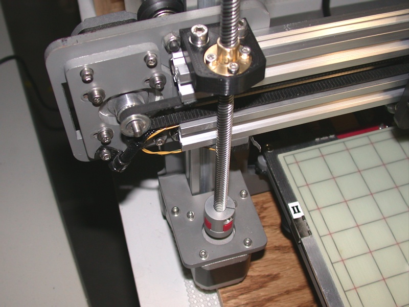
I haven't tested for a higher upper feedrate limit, but the i3v is currently configured and running fine with a Z-axis feed rate of 25mm/sec. That's quite swift compared to the original 5mm threaded rods. While the higher rate might help reduce time spent on layer shifts and lead to some marginal print quality improvement, the major benefit will likely just be in homing.
One brass nut in particular took a lot of shimming under one side for it to mount flush in the nut plate, and I had issues with the right-side screw being off-kilter from the vertical rail on that side when I mated the Z nut plate on that side to the x-idler plate. It appeared like the square hole on the x-axis idler plate for the Z-nut plate wasn't properly centered over the rail. Filing the hole wider and the tab on the nut plate narrower achieved the proper alignment. Until I can better understand what caused the misalignment, I'm holding off on posting the refinements I made to the Z nut plate to Thingiverse.Last edited by printbus; 02-03-2019 at 02:28 PM. Reason: typo


 Reply With Quote


Ender 3 Neo - Jam Problem
05-08-2024, 03:06 PM in Tips, Tricks and Tech Help