


Results 1 to 10 of 255
Hybrid View


-
05-30-2014, 12:51 AM #1Staff Engineer

- Join Date
- May 2014
- Location
- Highlands Ranch, Colorado USA
- Posts
- 1,437

Y Idler subassembly
Y IDLER SUBASSEMBLY
When I glued the wood parts together, I made sure the brackets for the idler pulley were perpendicular to the forward plate. This led to room for three washers with the bearings instead of the two used in the build video. I initially put the extra washer between the bearings, but when the Y axis components were assembled I noticed the idler brackets here are offset a bit from the bracket on the Y bed. I moved the extra washer to the side opposite of where the belt will ride.
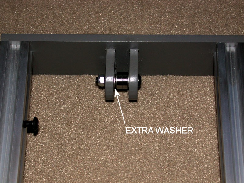
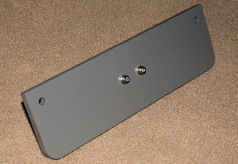
Gluing the brackets in place and filling the joints before painting leads to a clean look on the front of the printer. A disadvantage of this, however, is that I left no way here to adjust how the belt rides on the bearings. Normally, adjustment of the bolts holding the brackets in place could likely be used to slightly change the angle of the bolt with respect to the belt. The belt will tend to ride towards one side or the other if the bolt isn't exactly 90 degrees from the belt.
FOLLOWUP COMMENT: After using the printer a while, I haven't been having problems with the belt rubbing on the wood brackets, but there's a custom belt guide design now available on Thingiverse that is worth considering. I installed it after using the printer a while simply because it's a better design approach.
FOLLOWUP COMMENT #2: An improved version of the belt guide pulley is available at http://www.thingiverse.com/thing:790138Last edited by printbus; 05-31-2015 at 08:12 AM. Reason: Added mention of improved belt guide pulley
-
05-31-2014, 02:50 PM #2Staff Engineer
- Join Date
- May 2014
- Location
- Highlands Ranch, Colorado USA
- Posts
- 1,437
Heat Bed Installation
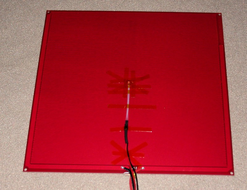
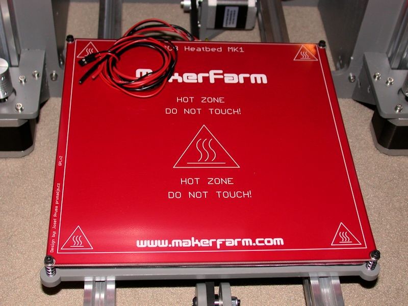
HEAT BED INSTALLATION
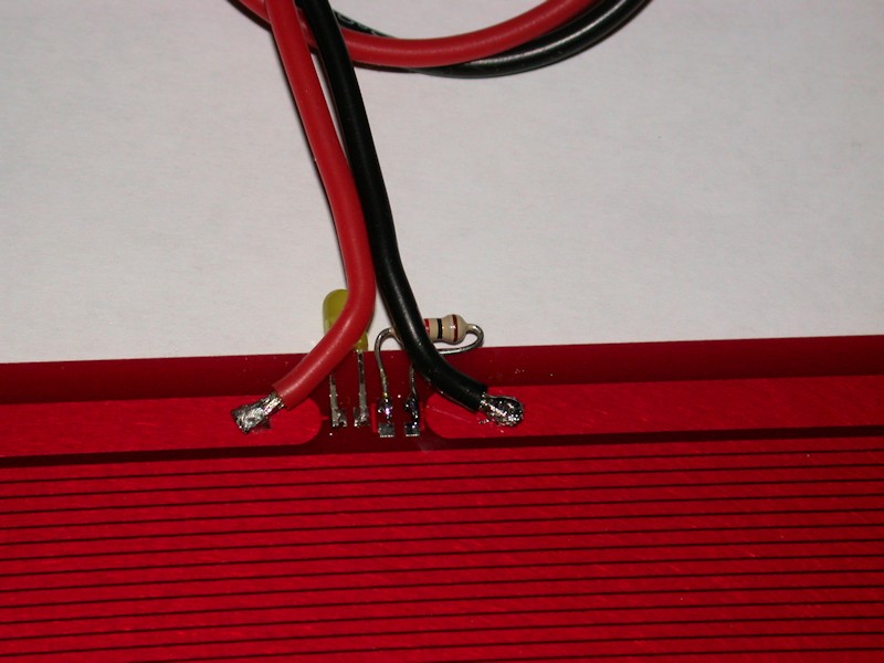
The MK1 heat bed has circuit pads for an LED and current limit resistor(s), and I opted to take advantage of that. The LED will face the rear of the printer, but I like the idea of having a visual indicator that there is in fact power being applied to the heat bed. I didn't have surface mount components on hand, so I tacked on a leaded-type T1 LED and 1K resistor. I also replaced the power wires on the MK1 with 18 gauge flexible silicone wiring. In addition to being very flexible, the high strand count of the wire will hold up better. Another trick from my RC helicopter hobby.
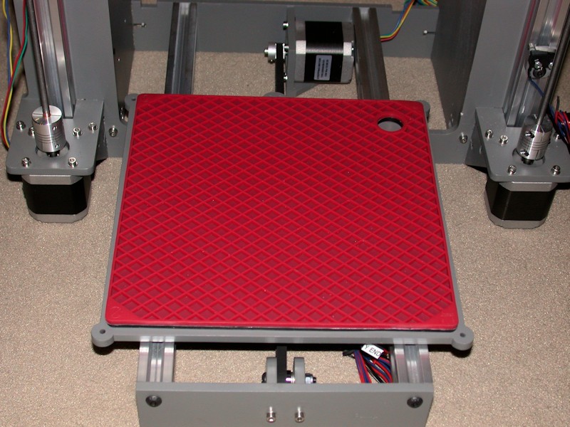
As an insulator between the Y bed and the heat bed, I picked up an 8-inch (200mm) square silicone pot holder/trivet from eBay to try. It's a perfect fit for the heat bed. This has a mesh pattern on both sides, and I trimmed away some of the mesh ribbing on one side to clear the bolt heads on the top of the Y bed. The silicone pad is thicker than what the typical piece of cardboard or cork sheet would be, so I had to increase the nylon spacer in the rear right corner to 3/8-inch. 3/8 of an inch might still be a bit short. I'll convert over to cardboard or cork if I end up needing that printable height loss back at some point.
FOLLOWUP COMMENT #1: In the later post on BED LEVELING, I describe how I revamped the approach to mount the heat bed to the Y bed. All four corners are now equipped with a spring. Longer and fully threaded M3 x 30mm bolts were used and a locknut is used to fix the bolt to the heat bed. Thumbwheels used on the bolts extending through the Y bed to provide a fast, tool-free means of adjustment.
FOLLOWUP COMMENT #2: For a printing surface, I had the local Ace Hardware cut some 1/8-inch glass to 8-3/8 inches square, roughly the same size as the heat bed. They wouldn't cut the angled corners needed to clear the mounting bolts, so I used a wet tile saw with a diamond blade to carefully cut them. I figured if the tile saw can cut glass embedded in mosaic tile, it would likely cut the glass better than I could do with a scribe. A bit of effort with a sanding block softened up the edges around the entire glass plate.
FOLLOWUP COMMENT #3: After using the printer a while, I realized the binder clips used to clamp the glass print surface to the heat bed rub on the heater traces on the bottom side of the heat bed. While I've never heard of anyone reporting wearing through the protection on the heat bed and shorting trace loops with metal binder clips, next time I have the heat bed assembly apart I'm going to add some kapton tape along the bottom sides of the heat bed as an extra precaution.
Last edited by printbus; 05-03-2015 at 07:43 AM. Reason: migrated to offsite image storage due to 3DPrintBoard issues


 Reply With Quote


Qidi X Plus 3 Paper thin first...
05-27-2024, 01:15 AM in General 3D Printing Discussion