


Results 1 to 10 of 255
Threaded View


-
05-30-2014, 02:37 AM #9Staff Engineer

- Join Date
- May 2014
- Location
- Highlands Ranch, Colorado USA
- Posts
- 1,437

X Axis alignment
X AXIS ALIGNMENT
While parts of it are, this overall procedure isn't in the build guide. After installation of the X-axis, it occurred to me it would be easy for the X axis to be out of alignment when all the associated hardware was tightened. While manipulating the Z-axis threaded rods can later provide some adjustment to this, I wanted to ensure things were aligned fairly well to start with. Here's what I came up with for an alignment procedure. This sounds complicated, but it really isn't when you're going through the process on the printer.
- Loosen the four bolts at the rear of the X motor and X idler. Following the earlier post, the eccentric spacers for the X motor and X idler should already be in the "loose" position. Now also make sure the eccentric spacer on the X carriage is also in the loose position.
- Verify that the distance between the upright aluminum rails is the same at the top and bottom of the rails. My 6-inch calipers couldn't measure this, but they could measure the gap left after starting with a short metal bar used as a filler. Mine were off a bit and I loosened the bolts on the rails, manipulated them some with a bar clamp, and then retightened the hardware.
- Adjust the eccentric spacer on the X motor (left side) so that all three wheels on the X motor grab the rails. The X motor plate should have little or no play when it is rotated back and forth.
- Now repeat this with the eccentric spacer on the X idler (right side).
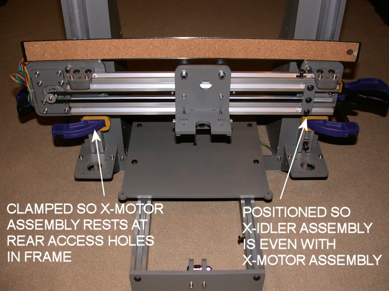
- Add a clamp to the left-side rail and rest the X motor assembly on it so that the four rear bolts on the X motor are accessible through the adjustment holes provided in the frame.
- Now hold a long straight edge (I used an 18-inch metal ruler) on the top edge of the X motor plate so that the straight edge extends to the X idler. Position the X idler so that the top edge of the X idler is also flush with the straight edge. Add a clamp to the right side rail for the X idler to rest on, keeping the X idler lined up with the straight edge.
- Now position the two horizontal rails the way you want them. For appearance, at least line up the ends of the two rails. The rails are a bit short; I positioned mine so there is an equal amount of T-nut exposed on both ends. Then tighten the four rear bolts on both the X motor and X idler. Recheck with straight edge and readjust as necessary. It took me a few tries to get this right, since tightening the hardware will tend to torque the X idler upwards. I ended up putting a bit of downward pressure on the X idler while I was tightening hardware.
- Install and/or tighten the brackets that hold the nuts for the Z axis threaded rods, making sure the X motor and X idler stay resting on the clamps. The nuts and/or threaded rods should not be in place yet.
- With the X carriage at the center of the horizontal rails, adjust the eccentric spacer on the X carriage so that all three wheels on the carriage engage the rails and the X carriage has minimal or no play when it is manipulated. Verify smooth operation of the X carriage across the length of the extrusions. If there are issues in getting a consistent feel (tight on one side, loose on the other, etc.), check for inconsistent spacing between the horizontal rails. Start over at step 1, using a clamp to slightly pull the rails together on the "loose" end.
- Install and/or tighten the X idler pulley bracket so it is vertical. Being exactly vertical isn't critical but why bolt it in place crooked? Watch for any interference with the Z nut bracket on the X idler subassembly. FOLLOWUP EDIT: I later trimmed off the corner edge of the pulley bracket so it doesn't catch on the Z nut bracket.
- Position the gear on the X motor so that the forward edge of the belt is at the forward edge of the horizontal rails. Adjust the belt tension by positioning the X motor in the X motor bracket. I positioned mine to take out any visible sag in the belt and then pulled it just a bit tighter. Tighten the motor mounting screws.
- Tweak how the belt rides on the X idler bearings by adjusting the idler pulley bracket slightly to the left or right. The rear end of the pulley bolt is fixed in the X idler. Moving the pulley bracket to the right (i.e., forward end of the bolt) will cause the belt to move to the rear of the bearings. Moving the bracket to the left will cause the belt to ride forward. Readjust the belt tension if required.
- Remove the clamps from the rails. Verify smooth and consistent Z axis travel. Recheck eccentric spacer settings on the X motor and X idler, and recheck for consistent spacing between the upright rails as required.
Note: Part of what we are hoping for here is perfect parallel alignment between the X carriage and the Y bed without the heater installed. I validated the above straight edge approach using a digital level (RC Logger pitch gauge from my RC helicopter hobby). It shows the difference between the Y bed and the X carriage rails is now within 0.1 or 0.2 degrees.
FOLLOWUP COMMENT: When the four bolts are tightened on the X motor mount and the X idler, you're defining the "natural" position of the idler with respect to the motor. Straightening this out later using the Z threaded rods will add a torque or torsion into the X carriage. It seems to me that if the torsion is high enough, it could help cause the Z motors to skip a step or double step. This is why I wanted to square up the x-carriage before the hardware is tightened.Last edited by printbus; 05-02-2015 at 11:53 PM. Reason: migrated to offsite image storage due to 3DPrintBoard issues


 Reply With Quote


Please explain to me how to...
Today, 02:43 PM in 3D Printer Parts, Filament & Materials