


Results 1 to 10 of 255
Threaded View


-
06-08-2014, 09:00 AM #11Staff Engineer

- Join Date
- May 2014
- Location
- Highlands Ranch, Colorado USA
- Posts
- 1,437

BED LEVELING
The bed leveling concept for the i3v seemed pretty straightforward. Adjust the Z endstop for the desired hot end clearance over the fixed-height home corner of the bed, and then adjust the other three corners to match the clearance. Yeah, right. I found it impossible to adjust the Z endstop with any accuracy or repeatability, especially since even a slight change in the angle of the switch makes a big difference when you're adjusting to paper thickness clearance. When I lucked into a Z endstop position that might work, adjusting the other three corners was tedious, having to repeatedly move the bed and then switch between adjusting the height and checking clearance.
Rather than revamp the Z endstop design, here's what I implemented to provide an easier adjustment. The Z endstop will be left at a fixed height. All four corners of the heatbed are now adjustable; I found a spring somewhat like the other three to use on the home corner and removed the spacer. M3 x 30 bolts now used in each corner, with a locknut installed to fix the bolt to the heat bed so it won't rotate. Springs between the locknuts and the Y bed. The springs Makerfarm provided in the kit slip perfectly over the round end of the M3 locknuts. M3 wing nuts or thumbwheels under the Y bed for adjustment. Z endstop switch set generally where it should be for the spacer height that used to be in the home corner, and will no longer be adjusted.
Tired of spending money at the hardware store for this thing, I thought I'd try printing some M3 thumbwheels to use under the Y bed. I was surprised to no end when the first print I've ever done came out usable, especially with the Z axis stepper motor running with an indeterminate current limit setting because of the damaged driver board.
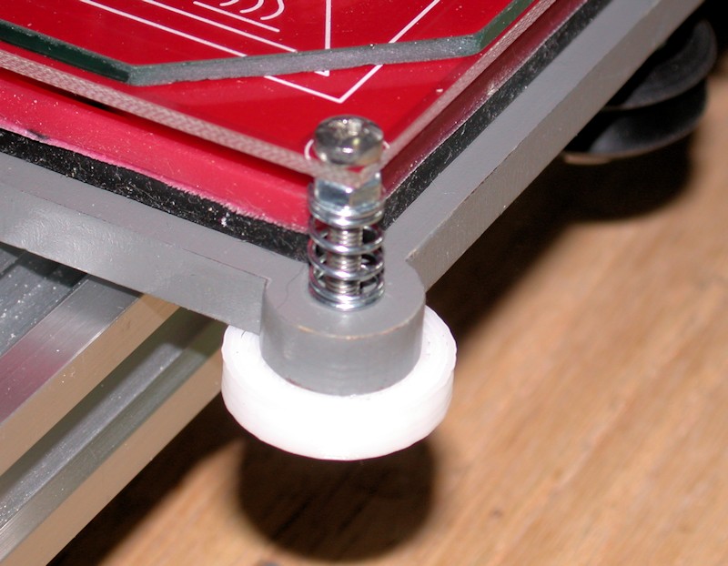
After adopting this approach, adjusting the bed for proper clearance in all four corners is trivial, and requires no tools. It took just a minute or two to tweak thumbwheels using a piece of paper for a gauge before subsequently printing my LCD knob. The surface area between the Y bed and the thumbwheels seems very adequate for keeping the thumbwheels in position.
I'm sure the concept of the thumbwheels isn't new, but I have no idea who to give credit to.
FOLLOWUP COMMENT: BTW, my bed leveling process starts with using the long straightedge to check for proper adjustment between the X motor plate and the X idler plate like I did during the X axis alignment. Z rods rotated as necessary to get them aligned with each other. I figure any mismatch from how I aligned them previously will lead to some torsion in the X axis, possibly increasing the chance of a Z motor skipping a step or doublestepping.
FOLLOWUP COMMENT #2: The design of the first M3 thumbwheels used includes a fine ridge for grip that didn't come out on my print. When I wanted to reprint the thumbwheels in black, I went for a different design with more a pronounced finger grip although I did have to file down the ridges a bit on the left rear position to clear the frame.
FOLLOWUP COMMENT #3: The Z endstop switch implementation was later revamped to a screw-adjustable design. That's a far better implementation.
FOLLOWUP COMMENT #4: The original post mentioned M3 x 30mm bolts being used in each corner. I think they are actually M3 x 25mm.
FOLLOWUP COMMENT #5: I later realized a significant advantage to the different design thumbwheels installed later. That design has 10 ridges around the circumference of the thumbwheel. With the 0.5mm pitch for the M3 hardware, this equates to 0.05mm in height adjustment for each ridge. In switching between printing directly on glass and then printing on painters tape, I can get very close to an initial adjustment by just rotating each thumbwheel by two notches to adjust the bed 0.1mm in height.
FOLLOWUP COMMENT #6: For those with 10 and 12-inch printers, note that the thumbwheel approach here is implemented on an 8-inch printer. For the larger printers to get the extruder to the front of the print bed, the rear of the Y-bed will need to extend beyond the rear frame brace that goes across the back of the printer. That rear frame brace may need to be modified to provide the additional clearance needed for the thumbwheels and/or the bolts used in the two rear corners.Last edited by printbus; 05-03-2015 at 07:20 AM. Reason: migrated to offsite image storage due to 3DPrintBoard issues


 Reply With Quote


Please explain to me how to...
Yesterday, 02:43 PM in 3D Printer Parts, Filament & Materials