


Results 1 to 10 of 255
Hybrid View


-
05-08-2015, 03:43 PM #1Staff Engineer

- Join Date
- May 2014
- Location
- Highlands Ranch, Colorado USA
- Posts
- 1,437

pgx3s, thanks for providing the PDF capture of the build thread. It was instrumental in figuring out how to restore missing images throughout the thread. All images should now be viewable again.
---------------------
SMOOTHIEBOARD AND OTHER UPGRADES
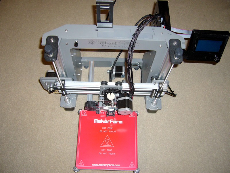
I don't plan to provide my usual level of detail, but I've subjected my i3v to a pretty substantial revamp. Here's a summary, with links to the applicable Thingiverse components.
- Improved X/Y belt idler pulley:http://www.thingiverse.com/thing:790138
- New approach for attaching X-belt to the X-carriage: http://www.thingiverse.com/thing:790207
- New approach for attaching Y-belt to the Y-bed: http://www.thingiverse.com/thing:796250
- Cover with power switch for the MeanWell power supply: http://www.thingiverse.com/thing:798560
- Revamped suite of Greg's Wade extruder and 9/47 herringbone gears: http://www.thingiverse.com/thing:812899
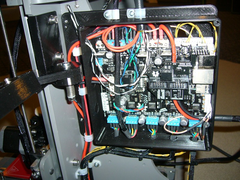
- Migrated to Smoothieboard electronics and Smoothieware firmware: http://www.thingiverse.com/thing:816676
- Migrated to Full Graphic LCD: http://www.thingiverse.com/thing:817274. Unbelievably, I had saved all the wood scraps from the original build, so I had the punch-out piece to stick in the top frame plate hole where the 20x4 LCD used to mount.
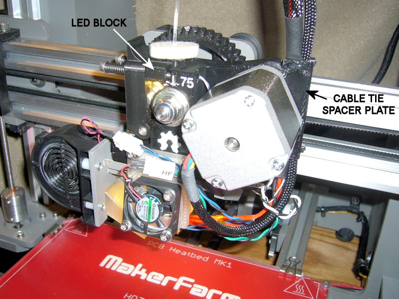
I also simultaneously migrated to the e3dv6 hot end and the new adjustable hobbed bolt from e3d. The above Greg's Wade extruder has been tailored for the nature of the shallow cut in the e3d hobbed bolt and for the PTFE liner on the 1.75mm filament feed in the e3dv6 1.75mm universal hot end. An additional thermistor hole was added on the opposite side of the e3dv6 aluminum block to keep all wiring on the right-hand side of the hot end. Since it worked well on my original build, Permatex Muffler Sealer was used again to bond the thermistor to the aluminum block. Instead of the provided thermistor, I'm using a US Sensor part number GP104L8F as what I think will be a better thermistor, although I've found it is extremely small and delicate. I broke one, so I'm running the thermistor that came with the e3d hot end on the heat bed. I'm using a 16mm heater cartridge instead of the 20mm one received with the e3dv6 so that I can continue to insulate the aluminum block with a couple layers of kapton tape.
The printer was basically rewired during the revamp, with all-new silicone wiring used for anything carrying much current. To minimize any noise issues, thermistors are connected with subminiature RG178 coax, endstops are connected with twisted pair wires, and motor winding pairs were also twisted before the motor wiring was rerouted. I equipped the Smoothieboard with screw terminals for everything but the thermistor and endstop connections. To minimize issues with stranded wire in the screw terminals, all stranded wires are terminated in a crimp pin or ferrule of some sort, giving the screw terminal something solid to bite into rather than the loose strands.
Unpublished at this time, I'm also using a custom fan shroud on the e3dv6. I reverse the airflow from that recommended by e3d so that the shroud fan pulls hot air off the e3dv6 heatsink and exhausts it with an upward angle that helps keep it of the print bed.
Last edited by printbus; 06-17-2015 at 02:11 PM.
-
05-08-2015, 08:40 PM #2Engineer-in-Training
- Join Date
- Jan 2015
- Location
- South Florida - Cooper City
- Posts
- 212
Looks good printbus...can you share your lcd mount?
-
05-08-2015, 08:48 PM #3Staff Engineer
- Join Date
- May 2014
- Location
- Highlands Ranch, Colorado USA
- Posts
- 1,437
The LCD mount is part of the GLCD frame, the last item in the bullet list. http://www.thingiverse.com/thing:817274 Originally Posted by voodoo28

-
07-10-2015, 05:15 PM #4Staff Engineer
- Join Date
- May 2014
- Location
- Highlands Ranch, Colorado USA
- Posts
- 1,437
Yeah, that was my idea too. Use the fifth driver for the second z motor, and if I ever migrate to a second extruder, I'll find a way to gang the two z motors in parallel.
-
12-30-2016, 11:53 AM #5Staff Engineer
- Join Date
- May 2014
- Location
- Highlands Ranch, Colorado USA
- Posts
- 1,437
E3Dv6 SILICONE BOOT CLARIFICATIONS
I better clarify my use of the e3d silicone boot before someone points out the boots don't fit older e3dv6 hot ends like I had installed.
In the original e3dv6 design, wires from the hot end thermistor were held against the aluminum block with the head of a lightly tightened screw. e3d has modified the e3dv6 to use a cartridge type thermistor that is held in place with a set screw. The silicone boots don't fit over the screw used with the thermistor wires in the original design.
Fortunately, I hadn't used the thermistor wire screw in my e3dv6 installation. I wanted the thermistor wiring to exit the right side of the aluminum block, not the left side as intended by e3d. The 1% thermistor rated for 300 degrees that I opted to use instead of the 3% one supplied by e3d also turned out to be microscopic compared to most thermistors, and I didn't feel the e3d installation approach would work well with it. So, I drilled a small thermistor hole on the right side of the block and permanently bonded the thermistor in the hole using the same muffler cement that I had used with the original hexagon hot end.
It turns out that the thermistor hole I had added on the right side was pretty close to where the cartridge hole is in the new block design. To use the new silicone boot, all I had to do was add a short slit in the side of the notch in the boot intended for the cartridge wires.
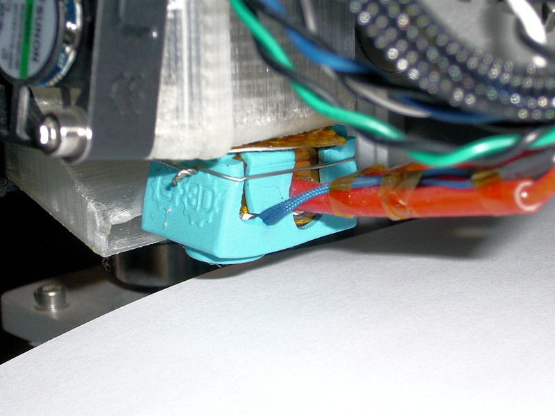
Fit of the silicone boot on my aluminum block is less than perfect, perhaps due to the fact that I installed it over existing layers of kapton tape already insulating the block. I added a loop of wire around the boot to ensure it stays in place.Last edited by printbus; 02-20-2017 at 06:01 PM. Reason: migrated to image stored offsite from 3dprintboard


 Reply With Quote


Qidi X Plus 3 Paper thin first...
05-27-2024, 01:15 AM in General 3D Printing Discussion