


Results 1 to 10 of 255
Threaded View


-
05-31-2014, 03:48 PM #11Staff Engineer

- Join Date
- May 2014
- Location
- Highlands Ranch, Colorado USA
- Posts
- 1,437

Extruder and Hexagon Hot End
EXTRUDER AND HEXAGON HOT END
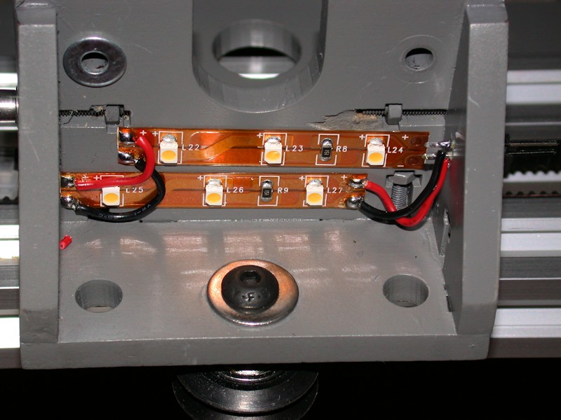
Before I added the extruder assembly to the printer, I opted to add some lighting to the X Carriage. There's a perfect area underneath it for mounting some adhesive strip LED lighting. I used two sections of 12V warm white LED strip lighting that I had leftover from a prior artwork project. A two-pin header was added to the sidewall of the X carriage extruder bracket for use as a connector on the LED wires. I thought about just tying the LEDs into the extruder fan power, but decided to run dedicated lighting wires in case I want to put the LEDs on a switch or dimmer circuit. I plan to sleeve the bundle of wires leading to the extruder assembly, and having a connector on the LED wires will allow me to disconnect the LEDs when I remove the extruder and cable harness from the X carriage for repair or cleaning.
FOLLOWUP COMMENT: A picture showing the heat bed illumination from these LEDs is here.
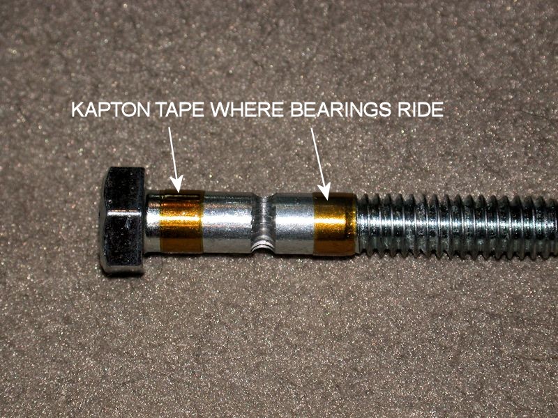
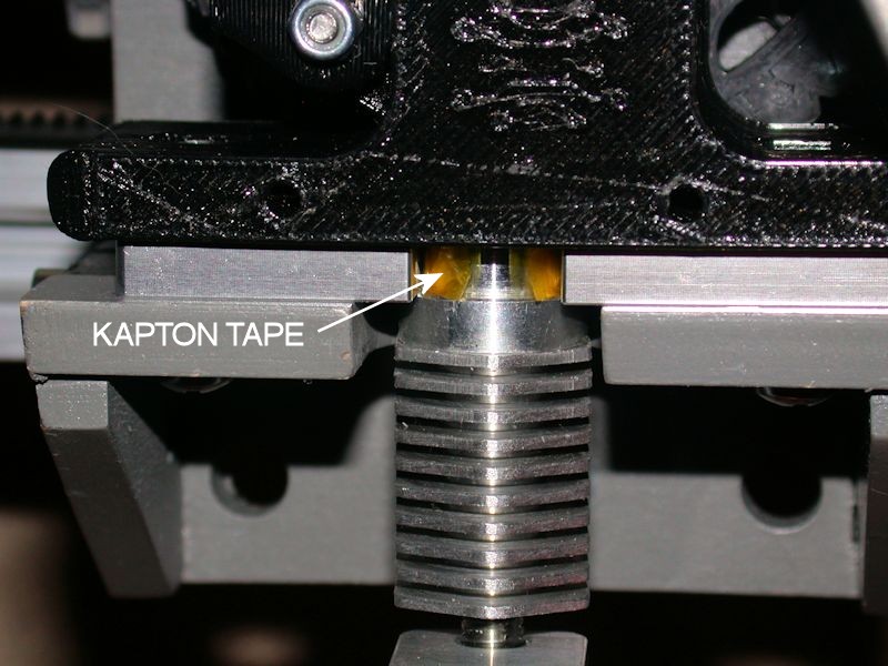
A locknut was used instead of the provided standard nut on the filament release pivot bolt. My printed parts seemed to have a looser fit than those in the build videos. After assembling everything I was disappointed to find a lot of sloppy mechanical play in the extruder tip. Multiple things were done to fix this. To improve how the bearings fit in the extruder, I added a layer or two of kapton tape around them. To minimize slop in how the hobbed bolt fits in the bearings, I added three or four turns of tape to the bolt where the bearings ride. The hex hot end was also a very loose fit in the aluminum mounting plate, so I added a layer of kapton tape to the post of the hex hot end. After final assembly, the extruder tip now has zero play.
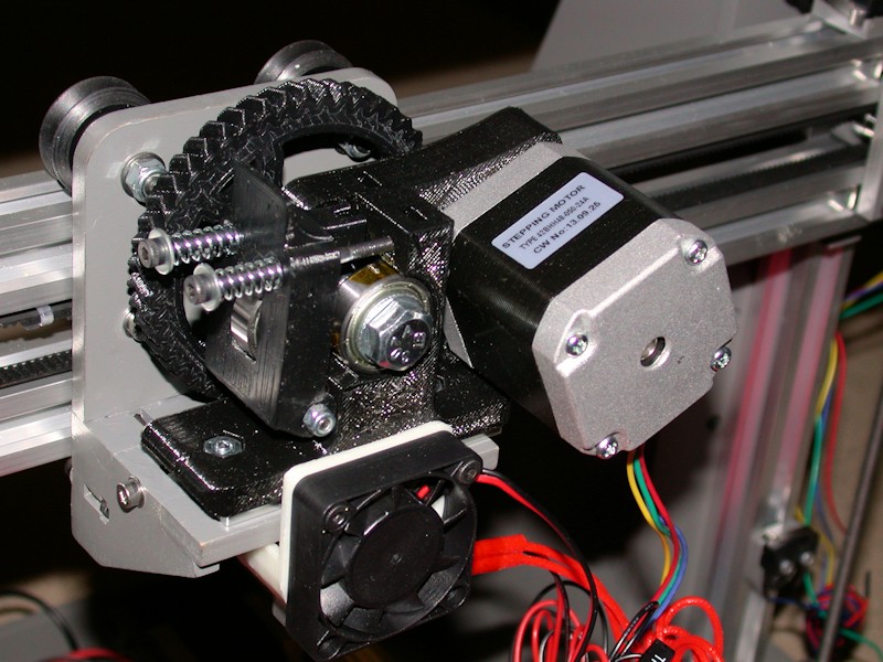
Envisioning how I plan to route wires, I oriented the extruder motor so the wires exit differently than shown in the build video. I found it necessary to lengthen the elongated motor mounting holes in order to obtain good gear mesh, at least with the gears in new and unused condition. M3 x 16mm bolts and M3 fender washers were used on the extruder motor instead of the provided shorter ones that are intended to recess into the wall of the extruder. The face-mounted fender washers should improve the hold as heat from the extruder motor starts to soak through the motor mount. Watch for conflict between the left motor mounting screw and the large gear; use of a button head screw will help reduce the size of the screw head.
The build video discusses the user printing a fan shroud for use with the hexagon hot end. A shroud was included with the hex hot end I ordered with my i3v. I found it challenging to add the shroud and fan on the bench with the hot end and aluminum plate still loose. I ended up mounting the extruder and hot end to the printer and then installing the fan and shroud. I had to enlarge the holes in the shroud for M3 bolts to pass through it.
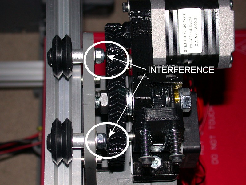
FOLLOWUP COMMENT #1 - I later realized that since I had added more washers than usual under the large gear to clear my face-tightened motor mounted screws, the large extruder gear was now rubbing against the ends of the bolts for the top two wheels on the X carriage. I ended up fixing this by shortening the bolts with a file so they don't protrude from the lock nuts when they are installed.
FOLLOWUP COMMENT #2 - I applied it later in the assembly, but I followed the ZennmasterM recommendation of using Permatex Muffler & Tailpipe sealer to thermally bond the thermistor to the hexagon hot end. ZennmasterM's use of a syringe would be overkill for the hexagon front end; all I did is dab a bit of it into the dimple provided for the thermistor with a straightened paper clip. After all my wire and cable routing was complete, I redid the kapton tape over the heater and thermistor wires. With wire movement now fairly over, this is when I applied the Permatex sealer.
FOLLOWUP COMMENT #3 - In response to some suggestions I found elsewhere on the web, I've reversed the hot end fan so that it is pulling heat away from the hot end and exhausting it out the front of the printer. This reportedly works better than pushing cool air into the "boxed in" bottom part of the i3v X carriage.
FOLLOWUP COMMENT #4 - The stock shroud for the hex hot end is mounted with the two screws for the hot end cooling fan. The shroud also sort of snaps onto the aluminum barrel of the hot end. I'm not sure what the intent is since that causes the bottom of the shroud to melt where it touches the aluminum block of the hot end. I've subsequently printed the shroud in ABS and cut away the bottom of shroud so it just barely clears the aluminum block of the hot end. This has eliminated the problem with the shroud melting. Having the shroud only supported at the top led to an occasional vibration at some print speeds. This was fixed by adding a silicone isolator between the shroud and the fan.
FOLLOWUP COMMENT #5 - The stock extruder comes with #6 Phillips head screws for mounting to the X-carriage, with nuts that are recessed into the printed extruder base. I replaced the #6 hardware with M4 cap screws, long enough that fender washers and nyloc nuts can be used on the face of the extruder base. I used M4 x 25mm. Cap screws are easier to tighten than Phillips head. Using fender washers on the face provides a lot more surface area that should hold up better to any heat making it's way up from the hot end. Using nyloc nuts should help keep the hardware tight. The screw on the left side can accept a very large washer; I used a 3/16-inch ID washer there that is about 20mm in diameter, just about the same width as the base of the extruder. It's tricky to get the nylock nuts in place, but my hope is that this improved mounting method leads to messing with the mounting hardware less often.
FOLLOWUP COMMENT #6 - Some have had issues with the adhesive backing not holding on similar LED strips. Mine have held fine. I'm not sure if it is the fact that the LED strips I have used 3M branded adhesive or the nature of the painted surface. Adding the kapton tape to the aluminum u-channel has been tricky. In subsequent extruder rebuilds, I've been adding layers of kapton tape as required to the top, round end of the hot end, using the tape as a spacer to push the hot end down into the aluminum bracket.Last edited by printbus; 05-03-2015 at 12:21 AM. Reason: migrated to offsite image storage due to 3DPrintBoard issues


 Reply With Quote


Please explain to me how to...
05-13-2024, 03:08 PM in 3D Printer Parts, Filament & Materials