


Results 1 to 10 of 255
Threaded View


-
05-30-2014, 03:02 AM #5Staff Engineer

- Join Date
- May 2014
- Location
- Highlands Ranch, Colorado USA
- Posts
- 1,437

Z Motor
Z MOTOR
I don't want wires extending off the sides of the printer, so the Z motors were oriented with the wires exiting the motors to the rear. The wires will likely eventually be routed through holes added to the frame beside the aluminum rails.
Consideration was given to using M5 coupler nuts at the threaded rod nut brackets. These would be long enough that they stick out of the brackets, allowing the nuts to be bonded to the brackets and/or aluminum rails with hot glue or other adhesive. I opted to not do this, but I'll put in the coupler nuts if I see issues with the standard nuts being loose in the brackets.
FOLLOWUP COMMENT: I'm sure the nuts are loosely held in the nut brackets as a safety measure. If the X-axis is lowered too far and the extruder hits the print bed, having the nuts loose will simply cause them to pull out of the nut brackets instead of damaging the extruder, the print bed, or binding up the Z-motors. That would be something to consider before bonding the nuts into the brackets.
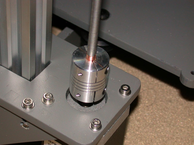
Flexible 5mm x 5mm shaft couplers purchased from MakerFarm were used to attach the threaded rods to the Z motors instead of the plastic tubing. Normal thread specifications allow some fit tolerance, so the threaded rods are a bit less than 5mm diameter. To improve the coupler grip on the threaded rods, I added a single layer of metal adhesive tape to the rods. I used some copper shielding tape I had, but something like foil HVAC tape should work as well. Regular foil would work too, but the adhesive backing is handy during installation. Anything metal will likely hold up better to the rod threads than vinyl tape, etc. In other threads, I've suggested wrapping the threads with the right gauge wire as a means to thicken up the rods. That sounded like a good idea at the time, but I didn't have much luck with that. In another thread, Old Man Emu pointed out there's another coupler design that uses grub screws to hold the shafts. They're probably the best way to go. Use of these couplers does require a ball-end 3mm driver to be used with the stock location of the Z endstop switch.
FOLLOWUP COMMENT: After using the printer a few months, I definitely suggest looking for the flexible shaft couplers with a pair of set screws to hold the shafts instead of this clamping style. While I didn't observe any issues in the printing quality, I did notice one of the threaded Z-rods was no longer tightly clamped in the coupler. I ended up tapping both of my couplers for an additional set screw on each shaft. It sort of boils down to "buy it right or buy it twice." More info on this is available in TWEAKS TO THE COUPLERS ON THE Z-AXIS RODS.
I added threaded knobs to the top of the Z rods. I felt there's a bit of an eye safety issue in having the top ends of the rods exposed, and preferred the appearance of actual knobs over wing nuts. The knobs I used are Grainger 3GFJ3. The knob on the left might get in the way of the provided top-side spool mount if I use it. I'll deal with that when it becomes a problem.
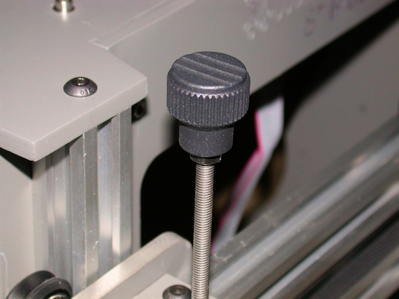
FOLLOWUP COMMENT: After I could raise the X axis to the top and check for clearance using the Z motors, I lowered the knobs as far as I could both for appearance and for minimizing conflict with the stock spool mount. I'm only losing usable height of about the thickness of the jam nuts under the knobs.Last edited by printbus; 05-03-2015 at 12:03 AM. Reason: migrated to offsite image storage due to 3DPrintBoard issues


 Reply With Quote


Please explain to me how to...
Yesterday, 12:15 PM in 3D Printer Parts, Filament & Materials