


Results 1 to 10 of 255
Hybrid View


-
06-03-2014, 12:53 AM #1Staff Engineer

- Join Date
- May 2014
- Location
- Highlands Ranch, Colorado USA
- Posts
- 1,437

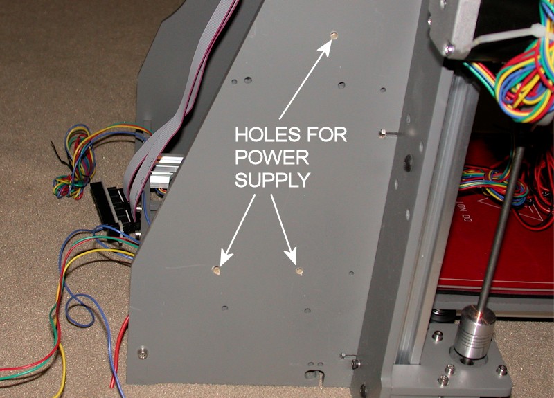
POWER SUPPLY AND RAMPS MOUNTING
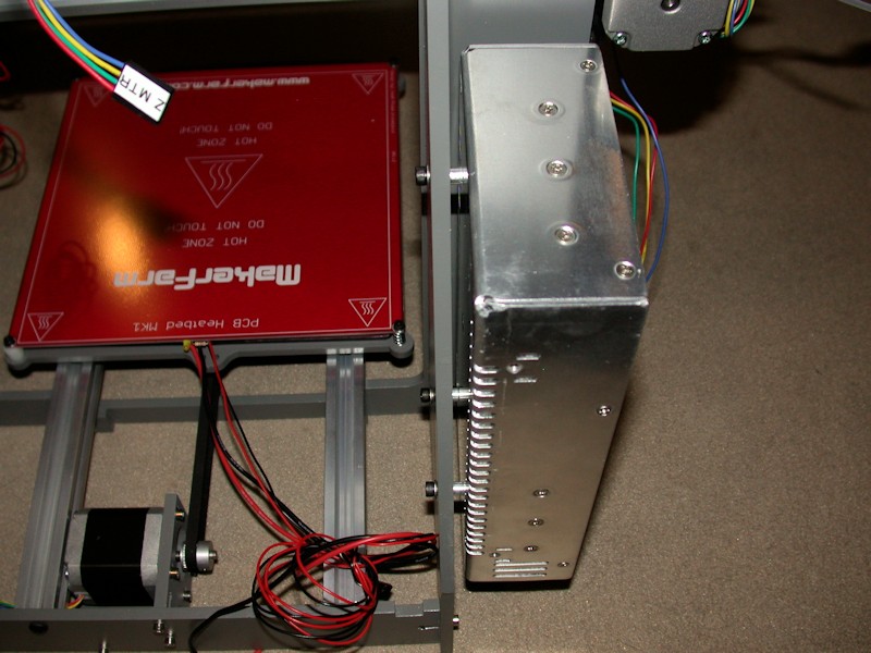
I ended up not using the holes MakerFarm provides on the left sidewall for a Mean Well type power supply. I moved the power supply rearward a bit to open up the airflow slots on the forward edge of the power supply, and I moved the power supply upward in order to provide more wiring access room at the power supply terminal block. This does mean, however, that the power supply is now only mounted at three points.
I also used #8 x 1/4-inch aluminum spacers on the power supply in order to open up the airflow slots on the mounting side of the power supply. I'd rather the power supply fan run as little as possible, and I'm hoping these changes improve the cooling obtained just by convection.
The RAMPS and heater relay were mounted in the provided holes. I threw spacers on these too, mainly so I could tuck wires under the boards.
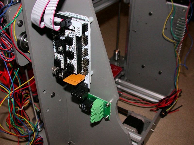
FOLLOWUP COMMENT #1: One of my tougher vibrations to track down turned out to be on the RAMPS board. The two large yellow square components (polyfuses) were touching, and at certain print speeds they'd rattle. To fix that, I added a dab of hot glue between them to ensure the two components aren't touching.
FOLLOWUP COMMENT #2: If you're downloading the Marlin firmware at this point in your build, DO NOT follow the instructions in the build guide RAMPS firmware video on where to get it. I learned the hard way that will get you the firmware intended for the i3, not the i3v. There are some subtle differences in the firmware configuration files. Obtain the files from the RAMPS download link provided in the i3v build guide.Last edited by printbus; 05-03-2015 at 07:03 AM. Reason: migrated to offsite image storage due to 3DPrintBoard issues
-
07-19-2014, 10:54 AM #2Engineer
- Join Date
- Jul 2014
- Location
- Eastern Colorado
- Posts
- 536
Huh, so that's what those holes are for. My heat bed relay melted when I was still using the i3, and I haven't fixed it yet. I've been using the relay mount holes as a place to zip-tie up the cables for the heat bed. Originally Posted by printbus

-
07-20-2014, 03:41 AM #3Staff Engineer
- Join Date
- May 2014
- Location
- Highlands Ranch, Colorado USA
- Posts
- 1,437
Yep. I can't speak to the i3, but the i3v build guide mentioned that's what the small hole pattern was for. The frame could stand a few holes for adding zip ties at both the RAMPS and heater relay; I thought about drilling some but ended up using 1/4-inch cable clamps instead. Originally Posted by AbuMaia


 Reply With Quote


Please explain to me how to...
Yesterday, 12:15 PM in 3D Printer Parts, Filament & Materials