


Results 1 to 10 of 255
Hybrid View


-
06-04-2014, 05:07 PM #1Staff Engineer

- Join Date
- May 2014
- Location
- Highlands Ranch, Colorado USA
- Posts
- 1,437

WIRE ROUTING (PART ONE)
Although there are a few things I'd likely do different, I'm pretty happy with how the wiring and cable routing turned out.
FOLLOWUP COMMENT: In response to issues others have had in understanding how to wire the heat bed relay, I've tried to provide some detail in thread Clarifying i3/i3v heat bed and heat bed relay wiring
Materials Used
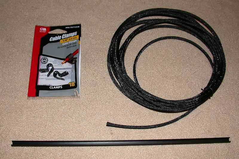
In addition to zip ties, I used (mostly 1/4-inch) expandable sleeving and a number of cable clamps to attach most of the wiring. Anyone who has used the expandable sleeving knows how frustrating it can be since it tends to unravel as soon as you cut it and try to feed anything through it. For this build I used "clean cut" sleeving I found on eBay that is a lot easier to work with. I also had obtained some aluminum rail slot covers from Openbuildpartstore. In addition to possibly being used for decoration, the slot covers can be used to create a wire raceway in the aluminum rails.
Every wire was custom fit to length, cutting off the connector and splicing it back on as required. I could have crimped new connectors on instead of splicing, but that would have required a lot of new contacts that I didn't have. Besides, almost all the heatshrink covered splices are now hidden inside the sleeving.
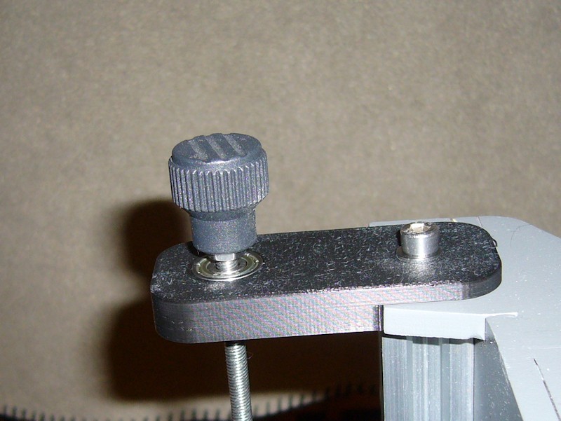
AC Power Switch
I added a push on/push off type power switch to the front of the printer.

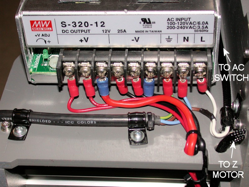
Power Supply Terminal Block
The power supply had three 12V and three return screws, so I routed three pairs of wires from the power supply to the other side of the printer. Heavy #14 wires were used for sourcing power to the heat bed relay. A dedicated pair of #18 wires provides power to the RAMPS board. An additional #18 pair fans out to low current loads like cooling fans and the LED lighting.
My power supply didn't come with any type of protective cover for the terminal block, so the AC connections are exposed. With time, I'll look into printing something to use.
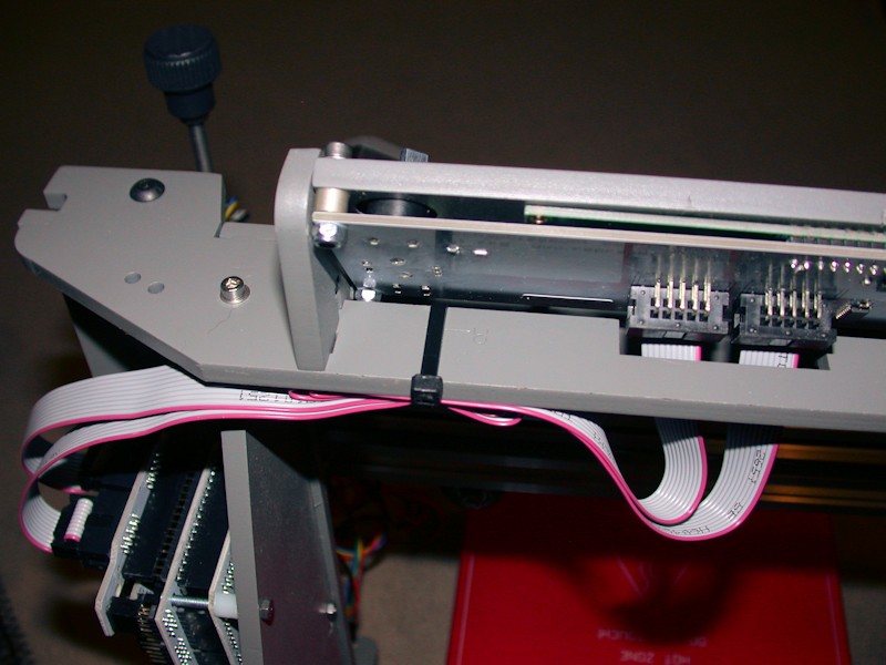
LCD Ribbon
I simply folded the excess ribbon from the LCD display and tied it to the upper member of the frame behind the LCD.
FOLLOWUP COMMENT: In the later GARBAGE DATA ON LCD DISPLAY post, I add a zip tie loop to pull the ribbon cables tight to the frame, away from the noise-laden bundle of wires from the X carriage that gets looped over the top of the printer. This helps reduce noise coupling into the LCD ribbon cables and messing up the screen.
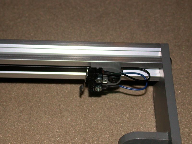
Y endstop switch wiring
Here I took advantage of the side channel of the aluminum rail and routed the wires through it. Wires are held in place behind a section of the black slot cover that was cut to fit. These wires get bundled with the wires from the Y motor at the back of the printer.
More routing info to follow... I've used up the five-pictures-per-post limit.Last edited by printbus; 05-03-2015 at 07:10 AM. Reason: migrated to offsite image storage due to 3DPrintBoard issues
-
06-11-2014, 01:55 PM #2Staff Engineer
- Join Date
- May 2014
- Location
- Highlands Ranch, Colorado USA
- Posts
- 1,437
HEAT BED CLIPS
Binder clips in the SMALL size are the common method of clamping the print surface to the heat bed. I found the MINI size works out better. Even installed all the way, they aren't as likely to protrude into the printable area. The smaller wire wings also keeps them from getting in the way, so they're easier to just leave on.

For a clip installed to the rear left side of the heat bed, bending the wings a bit allows the clip to clear the left sidewall of the frame. Leaving the wings in place makes it easier to remove the glass, so I'm likely to clean it more often.

MICRO sized binder clips are also available, but I don't think they open wide enough to grab both the glass and heat bed when using 3mm glass.
FOLLOWUP COMMENT: Note that I am using glass that goes from one edge of the heat bed to the other edge, or about 8-3/8 inches in width. This allows me to use clips that don't encroach into the print area, minimizing the chance that the hot end nozzle will hit a clip during homing, etc.
FOLLOWUP COMMENT #2: IIRC, I obtained the mini clips from the office supplies area at Walmart. I think they came in a package of 70 for $4 USD.Last edited by printbus; 05-03-2015 at 07:25 AM. Reason: migrated to offsite image storage due to 3DPrintBoard issues
-
12-01-2014, 10:31 PM #3Engineer
- Join Date
- Jul 2014
- Location
- Eastern Colorado
- Posts
- 536
I liked this idea, and incorporated it in my own printer. I've got the covers on the top slots of the Y rails, the front slots, bottom slot of the top rail and top slot of the bottom rail of the X rails, and the front slots of the Z rails. Originally Posted by printbus

I did have some trouble with the Z covers and the lower X cover moving. The Z covers slid down due to gravity, but the lower front X cover was moved by the bolt heads holding the X carriage extruder shelf rubbing against it. The Y covers are held in place by the wood pieces front and back, plus nothing rubs them.
For the bottom of the Z rails, and the ends of the X rails, I put a washer on an M5 bolt and screwed it into the threaded center hole of the rails. The washer is just large enough to hold the covers in place, since the M5 bolt head is not. I did try to superglue the covers in place, but that just left a white film on the covers, and didn't hold long anyway. The bolts are unobtrusive and do the job well.
-
01-15-2015, 12:31 PM #4Staff Engineer
- Join Date
- May 2014
- Location
- Highlands Ranch, Colorado USA
- Posts
- 1,437
NEW MOTORS AND MORE
Based on testing in Marlin Motion Related Configuration.h Settings for MakerFarm i3v that suggested the CW 42BHH48-050-24A motors from my older i3v kit were limiting my max Z feed rate, I opted to replace all the CW motors in my 8-inch i3v with more Kysan 1124090 motors. A Kysan has worked out well on the extruder for the last couple of months. Replacement of the motors was no easy feat since I had dressed and bundled all the printer wiring. The Kysan's have heavier gauge wires than the CW motors, so I didn't want to just cut off the wiring at the CW motors and splice on the Kysans.
The Kysans run cooler, so I took out all the motor fans and related wiring that had been added for the hot-running CW motors. Good riddance.
By leveraging additional torque provided by using 1/4 microstepping (1000 steps per unit for Z) instead of the MakerFarm default of 1/16 microstepping, the Kysans seem to be able to reliably drive the Z axis at over 3mm/sec feed rate. As an incremental increase, I'm now testing 2.5mm/sec for a while. This provides a worst-case Z home duration of about 90 seconds on my 8-inch printer.
Taking advantage of the disassembly required to swap out the motors, additional preventive maintenance was completed. The X and Y belts are now tighter than before, and I replaced both Z threaded rods and the Z nuts in the X-carriage. I worked to straighten the replacement threaded rods as best I could. To prevent accidents like the granddaughter grabbing one of the Z rods and bending it over, I've added support brackets at the top of the Z rods to protect them - http://www.thingiverse.com/thing:636381.
I've also been pretty aggressive in cleaning out the hexagon hot end nozzle a few times. Thinking I might have enlarged the nozzle tip in this cleaning, I wanted to replace the tip. Unfortunately, 0.40mm tips for the hexagon never seem to be available individually. I've installed a 0.40mm tip intended for use on the E3Dv6 hot end.Last edited by printbus; 05-03-2015 at 03:47 PM. Reason: migrated to offsite image storage due to 3DPrintBoard issues
-
01-15-2015, 12:58 PM #5Engineer-in-Training
- Join Date
- Mar 2014
- Location
- USA
- Posts
- 388
I hear you on this process! I totally redid my wiring and fixed some of the safety issues (soldering screw down power wires). It took forever but was definitely worth it to swap out our old hot motors for the Kysans . Originally Posted by printbus
Looks fantastic! Any chance you may be able to provide links to the replacement rods and nuts you ordered? I bent the tops of mine trying to get them into the clear plastic tubing the first time around and would like to swap em. Originally Posted by printbus
I ordered the 0.3mm hexagon tip from makerfarm and really like it. Could be worth a future try Originally Posted by printbus

-
01-15-2015, 01:02 PM #6Technologist
- Join Date
- Aug 2014
- Location
- Oklahoma
- Posts
- 191


With having a newer printer, with the motors that don't get hot, are the Kysan motors something to consider later on?
-
01-31-2015, 07:10 PM #7Staff Engineer
- Join Date
- May 2014
- Location
- Highlands Ranch, Colorado USA
- Posts
- 1,437
POWER MODIFICATIONS
These changes wouldn't be for everyone, but I wanted to modify how power is handled on my i3v printer:
- Provide capacity for 5V loads beyond what USB and the MEGA2560 on-board regulator can support
- Add a distribution scheme for 5V power other than connecting loads to RAMPS
- Be able to power up logic (MEGA2560 and LCD) without any fan noise being present
- Take advantage of Marlin provisions of power on/power off via LCD control or gcode
- Take advantage of Marlin provision for turning on extruder fan above a set extruder temperature
- Take advantage of Marlin provision for turning on RAMPS cooling fan when motors are being used
Use of an ATX power supply with a 5V standby output would have solved some of these expectations, but I didn't have a spare one that I wanted to use. I also preferred to keep the integrated feel of the MeanWell mounted on the i3v frame, so I came up with ways to adapt the MeanWell power supply to what I wanted. To provide a 5V source, I used a 5V 3A wall adapter that I had available. Yes, this will now require two power cords plugged into an AC outlet. I left the +5 connection disabled in my USB cable so that the MEGA2560 and LCD aren't powered by the USB connection.
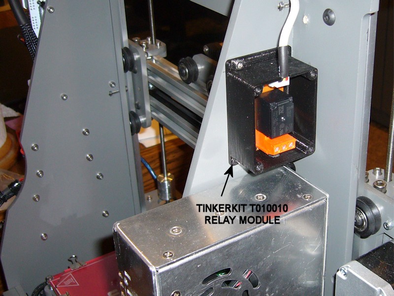
I added a Tinkerkit T010010 Relay Module inline with the AC source for the MeanWell power supply. This relay is controlled by the PS_ON signal on RAMPS. The custom case I created for the Tinkerkit Relay Module is available at http://www.thingiverse.com/thing:643351
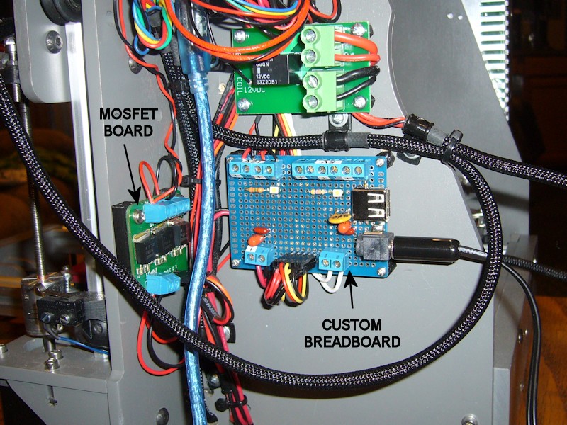
A MOSFET breakout board module switch relay (15A, 60V) 3-outputs for Arduino/PIC module from eBay was added to expand the 12V switching capacity of RAMPS. Inputs to the switch board are currently connected to D4, D5 and D6 on the RAMPS Servos connector, but I can repin connectors as needed in the future for AUX-1 or AUX-2 connections instead. The custom spacer developed for the MOSFET module is available at http://www.thingiverse.com/thing:1872958.
A custom breadboard was made to provide the necessary 12V and 5V connections and fanout. White SMD LEDs were used as power indicators, and I added a USB Type A connector for possible future use. I took advantage of building a custom breadboard and added both low frequency and high frequency decoupling capacitors to the board.
Marlin firmware changes associated with the wiring modifications include:
- Verified file pins.h has PS_ON defined as Arduino pin 12
- In file configuration.h, changed the definition of POWER_SUPPLY from type 1 to type 2 for an active-high power-on control and uncommented PS_DEFAULT_OFF so the 12V power supply starts in the off state
- In file configuration_adv.h, defined EXTRUDER_AUTO_FAN_PIN to Arduino pin 4 and set EXTRUDER_AUTO_FAN_TEMPERATURE to 35 so extruder fan is on any time the extruder reads over 35 degrees C
- In file configuration_adv.h, defined CONTROLLERFAN_PIN to Arduino pin 5
- In file ultralcd.cpp, rearranged the prepare menu so power control is at the top of the menu
I already don't like how the 12V power supply is shut off when host software connects to the printer and resets the MEGA2560. If I continue to find that unacceptably annoying, I'll add a diode-OR means of using another panel switch to force the 12V supply to stay on when I want it to. It would help if the folks at Simplify3D would have included a power control button in their machine control interface. I can consider migrating to a fabricated circuit board after resolving this and any other changes I want to make. The circuit board would likely include the MOSFET switches.
Marlin provides a speed setting for both the extruder fan and the RAMPS cooling fan. I was hoping to use those speed settings as a way to reduce fan noise, but found the PWM whine from anything other than full speed to be unacceptable. I'll have to look into how the high frequency PWM on the print cooling fan output is set up to see if I can replicate that on these fan outputs.
Here's an informally drawn schematic of the wiring changes -
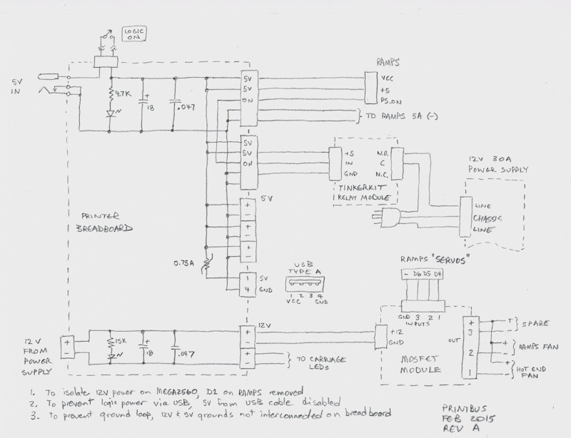
Last edited by printbus; 11-05-2016 at 03:49 PM. Reason: added link to spacer for MOSFET module


 Reply With Quote


Please explain to me how to...
05-17-2024, 12:15 PM in 3D Printer Parts, Filament & Materials