


Results 31 to 40 of 71
Thread: 3D Printed 3D Printer
-
07-29-2017, 10:56 PM #31Staff Engineer

- Join Date
- Jul 2016
- Location
- South Florida, USA
- Posts
- 1,248

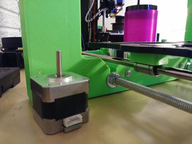
So I made the spacers for the threaded rods and got some hardware and got the y axis together..
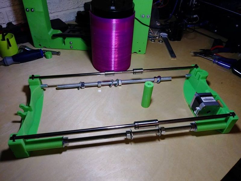
This build is moving along nicely. I am going to design my own z axis motor and top mounts because I want extra support around the smooth rod so it doesn't get loose over time because it is only pla. But I think the very next step is to get drive and idler pulleys set up and get a belt on this y axis..
-
07-30-2017, 06:20 PM #32Staff Engineer
- Join Date
- Jul 2016
- Location
- South Florida, USA
- Posts
- 1,248
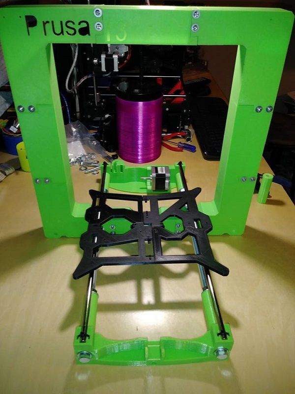
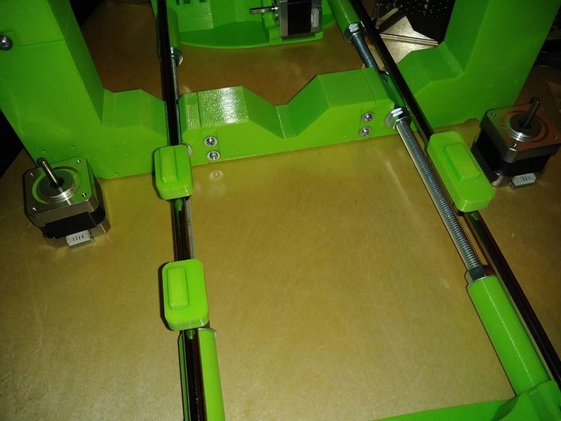
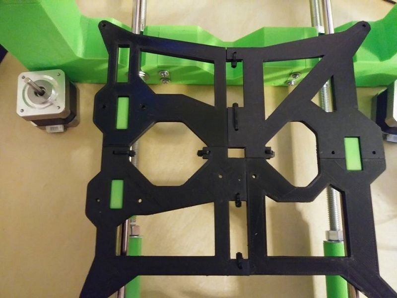
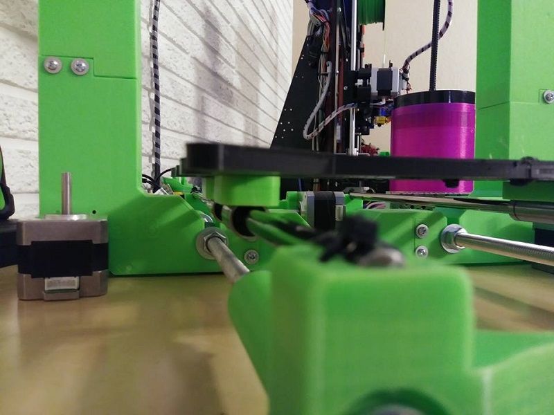
I have had a few problems so far with design snags. I mean having to make the spacers for the short rods was my fault and totally motivated by saving money. But I feel like the bottom of the frame is too tall and also the holes for the bearings to mount to the y carriage were not the right size and also not in the right place. My solution was to make 3 separate and very specific pieces to adapt the y carriage to the bearings used and their location..
And now the carriage can sit flat on all bearings..
The spacers I made also pick the carriage up 10mm. I know this will come at the cost of build height, but I had to get some clearance for the heatbed hardware to stick down..
-
07-30-2017, 08:00 PM #33Engineer-in-Training
- Join Date
- Jan 2016
- Posts
- 326
AutoWiz, Why don't you get longer rods to replace the short rods and spacers?
-
07-30-2017, 08:28 PM #34Staff Engineer
- Join Date
- Jul 2016
- Location
- South Florida, USA
- Posts
- 1,248
Because those 18" long 3/8-16 all threads were a dollar and change each at my local hardware store. The smooth rods are a setback as the cheapest I could find the set was $30. But even with that I am certain I can build this for under $50. The structure is rigid. And also because the frame and y ends were mismatched even though they were in the same thingiverse download. The frame is made for the usual 10mm threaded rods but the y ends only had 8mm holes. The bolts that are going in from the front and rear of the y ends are 5/16-18 and I designed the i.d. of my spacers accordingly.
Last edited by AutoWiz; 07-30-2017 at 08:41 PM.
-
07-31-2017, 04:44 AM #35Engineer-in-Training
- Join Date
- Jan 2016
- Posts
- 326
AutoWiz, I thought you get paid a lot of money for working on Corvettes. Why not build the new printer using aluminum extrusions? Aluminum extrusions should be much stronger than plastic.
-
07-31-2017, 05:20 AM #36Super Moderator
- Join Date
- Jul 2014
- Posts
- 8,818
Also cost more. :-)
I'm bloody impressed by the whole thing.
-
07-31-2017, 11:19 AM #37Staff Engineer
- Join Date
- Jul 2016
- Location
- South Florida, USA
- Posts
- 1,248
Aluminum extrusion build is here: Originally Posted by jeffmorris

http://3dprintboard.com/showthread.p...-250mm-X-300mm
Blindly throwing money at a printer can be seen here:
http://3dprintboard.com/showthread.p...Mixing-Printer
And my other printers can be seen here:
http://3dprintboard.com/showthread.p...twork-Printers
I have a theme to this build and that theme is building without money.Last edited by AutoWiz; 07-31-2017 at 09:10 PM.
-
08-03-2017, 05:41 PM #38Staff Engineer
- Join Date
- Jul 2016
- Location
- South Florida, USA
- Posts
- 1,248
Oh man. I know this thread is about my printed printer but I showed that white Z06 here and look what came in today..
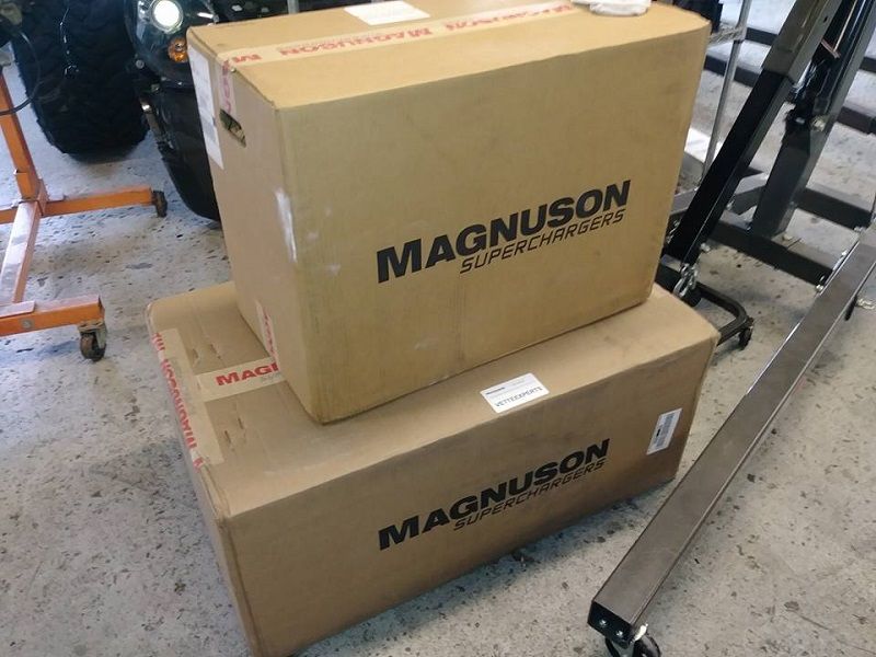
In anticipation of what is to come I parked the z06 on the dyno roller when we closed for the day..
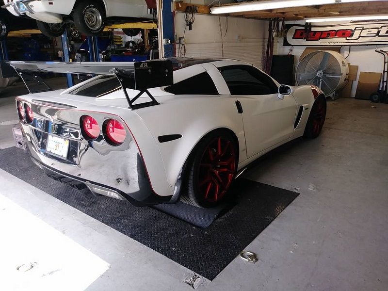
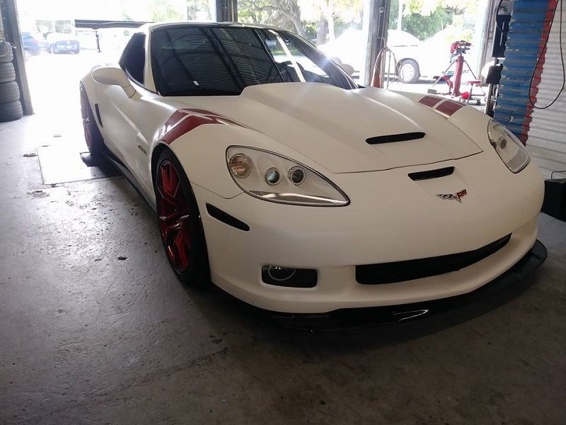
When this is done it should pull and sound very similar to this:
https://www.youtube.com/watch?v=kPQy2SF3ESw
....you know just because we have been here before. a few times:
http://www.digitalcorvettes.com/foru...d.php?t=242081Last edited by AutoWiz; 08-03-2017 at 05:59 PM.
-
08-03-2017, 06:11 PM #39Staff Engineer
- Join Date
- Jul 2016
- Location
- South Florida, USA
- Posts
- 1,248
And when I pulled the car out of the shop in the morning I parked the c6 right next to my c5..

Making my corvette look good. Not that my corvette is anything less than the best. Here is the crate lsx engine swap:
http://www.mp3car.com/forum/general/...corvette-droid
And the diff swaps are here:
http://www.digitalcorvettes.com/foru...d.php?t=245073
And aside from the gear change there was also a trans swap here:
http://www.digitalcorvettes.com/foru...d.php?t=265177
The track springs went in here:
http://www.digitalcorvettes.com/foru...d.php?t=264817
I am proud to pronounce my accomplishment that my corvette builds 476hp on 87 octane gas. and I get over 20mpg on the highway.Last edited by AutoWiz; 08-03-2017 at 06:21 PM.
-
08-06-2017, 08:51 PM #40Staff Engineer
- Join Date
- Jul 2016
- Location
- South Florida, USA
- Posts
- 1,248
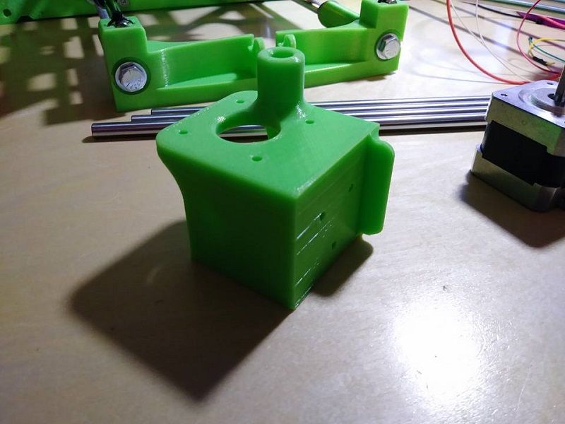
I drew up my own z axis motor mounts and I will draw up the top mounts after these are done printing. Here is the left side..
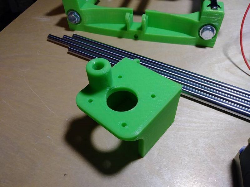
I put some extra material around the linear rod to make sure it stays tight. And I also put an angle on the backside so it hugs the side of the frame and has extra stability..
Here is the assembled x axis with e3d v6 hotend..
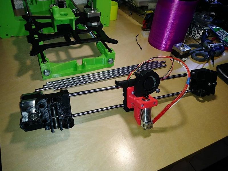
I can't put the x axis on until the rh z mount finishes printing, but here is where I am at now..
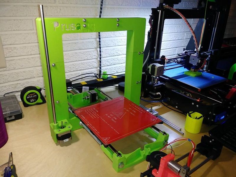
It's starting to look like a printer. The long linear rods for z are intentional. I am going to make the top supports in such a way that this printer will get more build height.


 Reply With Quote


Please explain to me how to...
Yesterday, 02:43 PM in 3D Printer Parts, Filament & Materials