


Results 1 to 10 of 101
Thread: Network Printers
Hybrid View


-
02-05-2017, 01:17 PM #1Staff Engineer

- Join Date
- Jul 2016
- Location
- South Florida, USA
- Posts
- 1,248

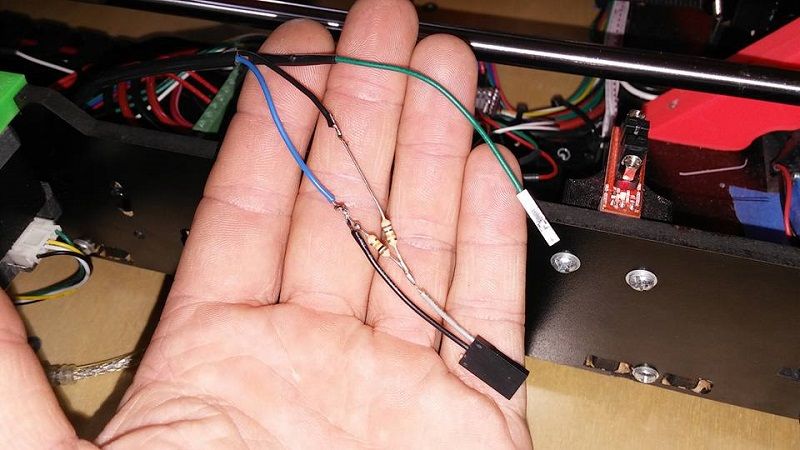
While I have the sensors mounted on 2 printers I am only wiring and changing firmware on 1 at a time. And I am starting with the homemade printer, Printilicious. The proximity sensor runs on 12v and the megatronics 3.0 board like all others uses 5v for it's sensors/end stops. So To resolve this I used a 10k and a 15k ohm resistor and made an in line voltage divider attached to the output wire of the proximity sensor..
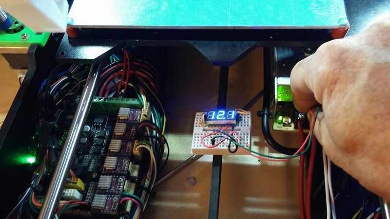
I took this as a weekend project and all of my dvom/multimeter/labscope and related diagnostic equipment is at work. So here is my makeshift voltmeter for testing my circuit..
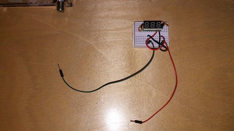
I got a stack of these tiny digital volt gauges off ebay a while ago and have used them for various projects. There is one mounted to each printer just so I can easily monitor the 12v output of my power supplies. They work great..
And today I am struggling with the trial and error of marlin settings.


 Reply With Quote


Please explain to me how to...
Today, 10:55 PM in 3D Printer Parts, Filament & Materials