


Results 71 to 80 of 95
Thread: 12" I3V Build
Hybrid View


-
03-03-2016, 11:37 AM #1Staff Engineer

- Join Date
- May 2014
- Location
- Highlands Ranch, Colorado USA
- Posts
- 1,437

Ah, I better understand the knob model now that you've described it. Well, inside circles add a bit of a problem in that they tend to "pull" the extrusion towards the center of the opening as the nozzle moves around it. On normal holes, this can make round holes come out undersized. On the knob, that slight pulling might have meant the new layer wasn't gripping the offset layer below enough and it pulled free. In other words, it's easier to build that overhang on a straight edge than it is on a circle. Another thought is that there's just a bit too much of a gap on the first layer. If there is, that can mean the 2nd layer can't print reliably and this can continue up through the model. Once one layer doesn't stick to the layer below, there's likely no way the layers above will ever recover.
I know what you mean about part dimensioning. The only design tool I've used is openSCAD. Anymore, I don't bother to print someone else's Thingiverse item unless they provide the openSCAD source for it, just in case I need to adjust something. I also typically avoid models where there's no photograph of a finished print. I found there's too many people out there who like to crank out designs, but they have no printer so the design is unproven. On knobs, then you have the issue of 1/4-inch vs 6mm shaft diameters. On push-on knobs, the two sizes aren't interchangeable.
Adding the single solid layer across an unsupported area where there will be a center hole is certainly a way to go. The Greg's Wade extruder body and large gear models I started with in my overhaul of the designs did that. I learned why the solid layers were there when I took the solid layers out of my earlier revisions. Even with support added in the slicer, the center hole just could not come out cleanly.
Picking up 3D printing as a hobby has been fascinating, but if I knew before that I'd be having to learn so much about nit details I think I would have passed on it.
-
03-02-2016, 02:45 PM #2Technician
- Join Date
- Nov 2015
- Posts
- 73
I thought about printing something to lock the bottom nut. I like the thumb wheel on the bottom better though as then the hotend and stuff around it will never be in the way trying to fiddle a hex key into the head of the screw and I don't need any tools, besides a piece of paper or my feeler gauge. Place the hotend over the part to be leveled, one hand on the feeler, other on the thumb wheel tweak till it just slides under. Got one that printed ok last night and got it installed. Works really well.
Wanting some feedback on what I should be changing to get my PETG prints better. Thought I was doing better than I apparently am when printing the idler pulleys. Am I under extruding, hotend temp too low or have I maybe leveled my bed with too much space to the nozzle?
https://goo.gl/photos/tBLiXoRCtCeVfUFN7
https://goo.gl/photos/6VU628gR7xVeJW4V7
-
03-02-2016, 04:24 PM #3Engineer-in-Training
- Join Date
- Feb 2014
- Location
- CT
- Posts
- 345
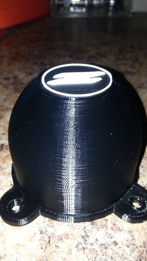
This was just printed PushPlastic Black PETG. .3 layer 260c extruder E3D Itty Bitty Flexv2. 60c bed 40% infill 3 solid outer and inner shells 4 solid top and bottom layers no brim no support.
-
03-02-2016, 04:17 PM #4Engineer-in-Training
- Join Date
- Feb 2014
- Location
- CT
- Posts
- 345
I run PETG @ 260 and 60 bed.
-
03-03-2016, 08:23 AM #5Technician
- Join Date
- Nov 2015
- Posts
- 73
Here's a pick of what has to be cut away in an IV3 12 for the thumb screws. This is the thinner of the two STL that printbus linked to.
IMG_20160303_075338965.jpg
260C and a 1.02 multiplier gave much better results with the PETG. Still not perfect but much better. I still get a bunch of loose strings in the nut capture area of the thumb screws though. Would a cooling shroud help PETG like it helps PLA?
-
03-03-2016, 08:34 AM #6Engineer-in-Training
- Join Date
- Feb 2014
- Location
- CT
- Posts
- 345
PETG is stringy
-
03-03-2016, 08:44 AM #7Technician
- Join Date
- Nov 2015
- Posts
- 73
Guess my terminology is a bit wrong, I do get some stringingness and i'm not really concerned about that, it picks off easily. This is more full bits of an extrusion string that doesn't attach where it should and ends up in the middle instead of part of the print where it should be. Happened on the LCD knob and these thumb wheels. Only on inside circles with a bit of overhang towards the middle.
-
03-03-2016, 10:51 AM #8Technician
- Join Date
- Nov 2015
- Posts
- 73
Saw that video before I even started building my printer. His cooling shroud is my next print. Although I'm not sure which one to print. Not sure if the short one will clear my v6 cooling fan or not.
I though the LCD nob should have done better and with the extrusion multiplier increased and the temp increased I think it might. As it's not really a bridge, more of an overhang as the outer nobs inside wall slopes up to the top (MatterControl didn't think it needed any supports when I tried to add them. The thumb screws on the other hand do have a bridge, and more problematic is the bridge is when the printer is printing in circles. Printing in a circle in the middle of no where seems to be an impossible problem (that fact it does as well as it does is really amazing I guess). I should see what MatterControl does when I add supports to that model. If I was to redesign it I think I'd design it so one or two layers are solid and the last few on the top have the hole in them. Then I could just drill it out. Hopefully the slicer would then do straight lines across the bridge gap that could then support the circles above and you'd have the mark for drilling it out after.
I'm definitely in the beginning of the learning curve. The biggest hurdle for me right now is to understand what settings to adjust to fix what problems. Feedback cycle is a little long so I'm asking questions to get pointed in the right direction to hopefully cut down on iterations before I get things moving in the right direction. I've been really appreciating the feedback I'm getting through this build. It's helped me sort a few things out much faster than I would have otherwise.
The other thing of note for the LCD knob and the thumb screws is i had to scale them down a bit to get them to fit properly. The thumbscrews to 0.95 and I forget what I scaled the LCD knob to, it was just under or just over 0.95. Guess I should design some of my own with dimensions I know or check the STL files in Sketchup and see the actual dimensions and compare. Guess i just figured I'd be good after printing the 200mm test bars and they came out to within 1/2mm.
-
03-03-2016, 11:53 AM #9Technician
- Join Date
- Nov 2015
- Posts
- 73
I'm not sure if I'm looking at this as a hobby or not. I'll be playing with it to get it printing as well as I can and to learn how to use it well. After that I wanted it as a tool. After the fan shroud my next print will be a clip on bracket that will prevent the connection between the hose to the tap and the filter housing in my drinking water filter from coming a part.
http://www.rainfresh.ca/drinking_water_system_1.php
It's just a pressure fit with an o-ring between two brass parts (f'n stupid design). They say it should stay together on it's own but the pressure in my house just blows it a part. Right now I have it wrapped in wire which is a pain when it's time to take it a part to clean the filter. So I plan to design a clip that's easy to slip on and off that holds it together. After that I want to design and print a custom case that will hold my glasses and sunglasses inside the pistol pouch part of this bag.
Then I've got all manner of things I want to print for my wood working tools (my fore ray into 3d printing all started with this). And the wood working tools started for building subs and speakers for hometheater but have been used way more in the last 10 years for renovating my house. So hobby vs not sure what to call it, I'm just not sure anymore :P
-
03-05-2016, 03:37 PM #10Technician
- Join Date
- Nov 2015
- Posts
- 73
IMG_20160305_154049118.jpg
Fan shroud printed quite well. Once I figured out I could remove one of the hotend mounting screws and pivot the fan to the back and then reinstall it I was able to mount the shroud without any extensions. This is the longer of clough42s two shrouds. I'll find out how it works later tonight or tomorrow.


 Reply With Quote


Please explain to me how to...
Today, 12:15 PM in 3D Printer Parts, Filament & Materials