


Results 1 to 3 of 3
-
10-18-2015, 01:44 PM #1Student

- Join Date
- Sep 2015
- Posts
- 9
GEEETECH Prusa I3 X - common issues - diagnostics and calibration - help thread
Prusa I3 X common issues / support thread - BETA - will be updated with more information and photographs soon
I will do my best to help anyone who posts here but I am in no way shape or form an expert
This topic will cover issues that will cause problems such as:
POST #1 MECHANICAL AND ELECTRICAL ISSUES
1.LCD panel not working / SD slot not working
2.Installation of drivers
3.Install working firmware malfunctioning firmware improper firmware
4.Z axis not moving, seizing, stopping, stuttering
5.Driven wheel / drive wheel not turning X axis belt seizing slipping Y axis belt seizing slipping
6.Filament not loading properly feeding improperly filament not feeding filament jammed mk8 jam
POST #2 MECHANICAL ISSUES CONT.
7.Hot end wires touching heat bed knocking print off of heatbed
8.Heat bed not level bad prints nozzle grinding
9.Extruder carriage not level bad prints nozzle grinding
10.Where to home / zero the extruder, how close to place the nozzle, how to home extruder
POST #3 3D PRINTER CONTROL AND SLIC3R SETTINGS
11.Print quality basics, slic3r settings, using repetier host, print is low quality, walls are not smooth, ETC.
12.Print isn't sticking, print is curling
So you have built your new prusa i3 x and it is NOT working, or NOT working to your expectations - please follow this list in order as you will need
to do EVERYTHING on this list before using your prusa i3x after assembly
MAKE SURE THAT YOUR MACHINE IS FULLY POWERED OFF BEFORE MAKING ANY MANUAL ADJUSTMENTS OR RESEEDING CONNECTIONS
1. LCD screen is unresponsive
Fix - Switch the place it is plugged in with the other cable coming off the back. Most guides will tell you to plug them into the mainboard exactly
backwards. there are only two, so just switch them.
see wiring section step 27 http://www.instructables.com/id/Buil...I3-X/?ALLSTEPS
EXP1 and EXP2 are the ports on the back of the LCD
LCD and SD are the ports on the mainboard
EXP1 (LEFT) is LCD
EXP2 (RIGHT) is SD
OTHER GUIDES ARE WRONG. THIS IS VERIFIED INFORMATION - I OWN THE PRUSA I3X.
2. Drivers aren't installing upon plug in
Fix - Enable automatic driver updates. Link below for windows and mac OS
http://www.geeetech.com/wiki/index.p...ll_the_drivers
3. Can't find proper firmware / Machine is alarming buzzing loud when I turn it on and won't stop making the sound until turned off
Fix - you need working updated firmware. Link is below. If you want to customize your firmware (motor speed etc) start with this file as a base.
PROTIP - save this firmware as an original file somewhere as a backup incase you mess up your firmware and need to reset it
THREAD - http://www.geeetech.com/forum/viewto...p?f=10&t=17046
I3X FIRMWARE DIRECT DOWNLOAD (str8 from geeetech.com!) - www.geeetech.com/forum/download/file.php?id=1584
use the arduino IDE to upload the firmware to your machine. google a guide if you aren't familiar with the program. (it's copy and paste don't worry!)
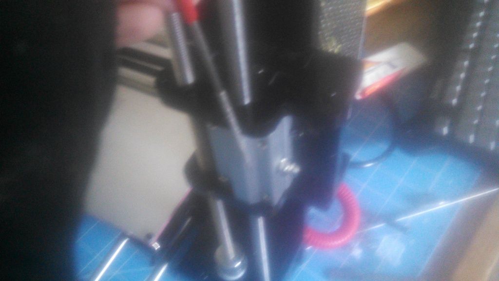
4. Z axis isn't moving, isn't working right, is seizing in certain areas
Fix-
1. SMOOTH RODS LOCKED UP - Use the file provided in the build kit to file the holes for the smooth rods larger. the smooth rods should go
through their carriage including the bearing without fighting it. if you have to shove it through the unit, keep filing. it should glide right through
on both sides. I shouldn't have to say this - but don't file it with the bearing attached unless you want to destroy it.
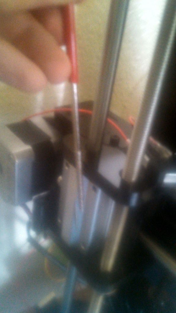
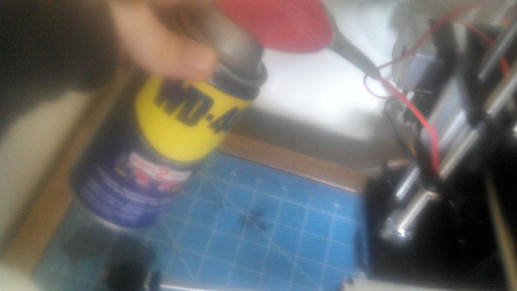
2. THREADED RODS IMPERFECT - Straighten by hand if neccessary. roll on table / put against a straight object to determine straightness.
Examine threading for imperfections. Apply WD-40 or anti-seize lubricant to threading and manually thread the rod a few times through the bad areas
3. When the rods are working - level the X axis. (see no. 8 no. 9) if it isn't perfectly level the motors will not work in unison! Once it is level and you can
move the axis with the motors with manual control in repetier host (or chosen program) continue to move the x axis up and down and work the threaded
rod for a couple hours applying more WD-40 as needed. when it is working smoothly all the way from the bottom to top you are ready to print.
4. X axis drive wheel is scraping against the Z axis body because the screw is too long - see No. 5 - DRIVE WHEEL RE-ASSEMBLY
5. Y axis isn't moving, isn't working right / X axis isn't moving, isn't working right, Z axis isn't moving, isn't working right / belts are slipping
and seizing / print quality is bad and I don't know why
FIX - RE ASSEMBLE THE DRIVEN WHEELS - The X and Y axis use belts. the belt goes on the motor at one end and a drive wheel at the other. Make sure
your belts are properly sized and when you tighten the drive wheel unit to the body it makes the belt tighten. The drive wheels need to be re-
assembled. The instructions call for an m4x25 screw to hold the wheel in place. However, this is too long for the X axis and will scrape against the Z
axis causing the Z axis to seize or stop. Follow the directions and photos below to fix BOTH of your drive wheel assemblies. I REPEAT - BUILD BOTH OF
YOUR DRIVE WHEEL ASSEMBLIES LIKE THIS INSTEAD OF THE WAY THE DIRECTIONS SAYS!!!!
1. use needle nose pliers or something like them to space the drive wheel holder a little further out. be careful not to break it. just a
little pressure will bend the part. try to heat it up with a heat gun or hair drier if you want to make it slightly more pliable before bending.
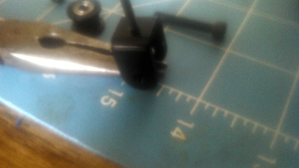
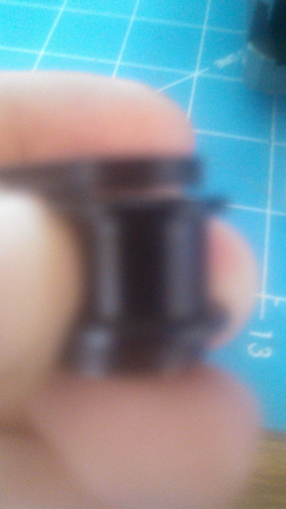
2. The bearing / wheel assembly should now slip in and out of the holder with no issue, but the gap shouldnt be too big. (see picture)
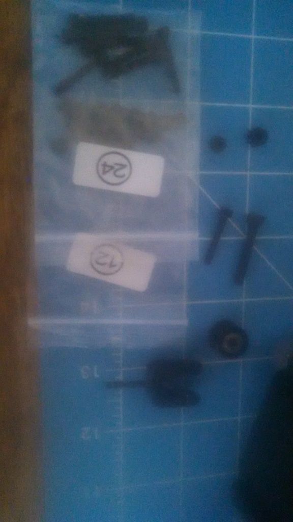
3. Replace the m4x25 screw and nut with an M3x20 screw and nut (#24 , #12). When you tighten the screw down, make sure that it tightens TO the
holder, and does not TIGHTEN the holder itself. the bearing drive wheel assembly should now turn freely. Re install both of them.
(NOTE: you may need to adjust your front plate when installing the new drive wheel assembly because the belts will be lengthened slightly after this process. Move the front plate forward to tighten the Y belt, and use the wingnut to tighten the X belt.)
6. I can't figure out how to load the filament / the filament is jammed
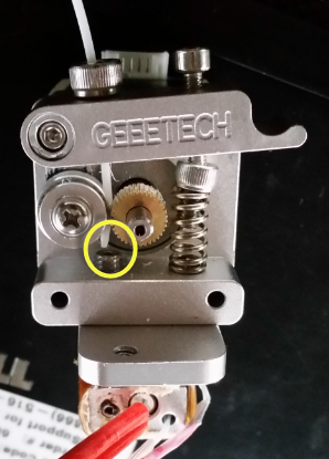
1. remove your fan and heat sink with a screw driver
2. press the lever on the front of the extruder, watch it move the bearing. this is how it locks the filament to the motor.
3. view the picture below, this is probably why you can't get filament through properly the first time (from thread
http://www.geeetech.com/forum/viewto...c8e0797a6e8bd5)
4. now that you know how it works, heat the extruder up, press the lever, feed the filament through the hole, keep pushing it until you see it
coming out of the other end melted. it takes a good amount of force, but don't try to push it through too fast for it to melt. remember its much
easier to push through if you hold the lever down because of the way it grabs the filament.Last edited by Ecological3d; 10-22-2015 at 02:25 PM.
-
10-18-2015, 02:08 PM #2Student
- Join Date
- Sep 2015
- Posts
- 9
RESERVED POST - COMING SOON - THANK YOU
7. How to modify your X axis extruder carriage to keep hot end wires from touching heat bed
1. Drill a 3/8" hole in the bottom right side of the extruder carriage between the bearing and the side wall
2. (optional: file the hole, then cover end of wires with electrical tape to avoid damage) now feed the wires through the hole, the optional electrical tape should be through the hole (this prevents wire damage by filling the hole with tape and stabilizing wire)
3. Mount the extruder while pulling the wires through the hole simultaneously. this is a little tricky but you can work it.
4. (optional) use electrical tape after each bend in the wire pack to keep them together, enjoy your wires not touching the bed.
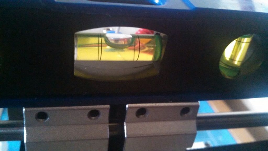
8. How to level the heat bed
1 / 2. place the level parallel to the X axis, on either side of the extruder carriage. adjust with wingnuts to level.
3 / 4. place the level at a 45 degree angle to the X axis (corner to corner on your heat bed) move the extruder carriage to either side, or up, to accommodate for size of level
Repeat this process until the bed is fully level between each corner and each side
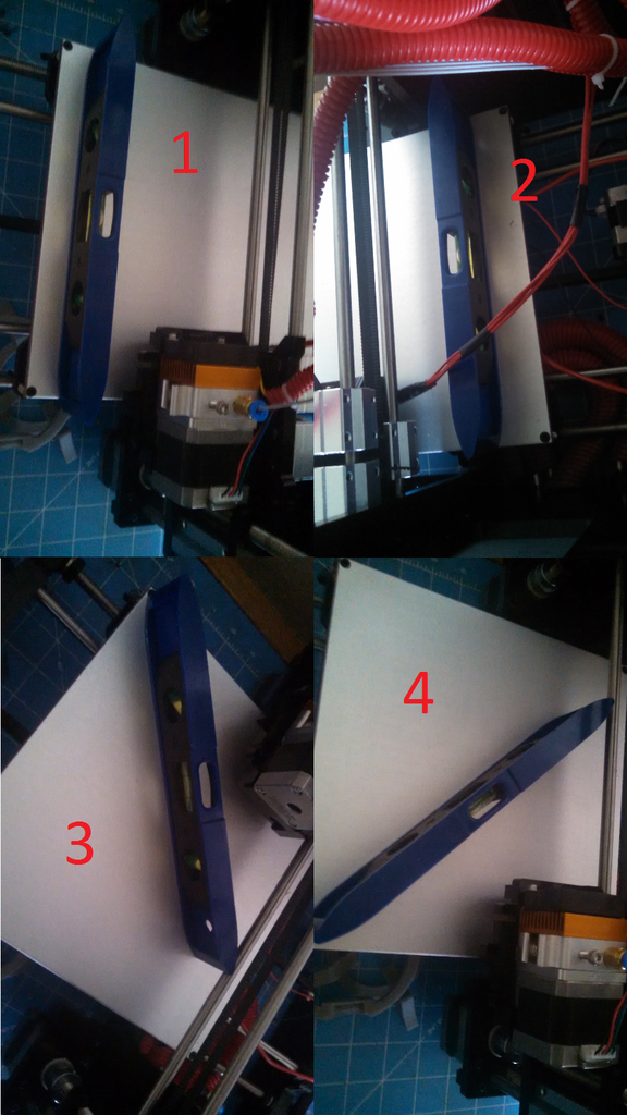
9. How to level the extruder
1. Place the level on the bearings of the extruder x axis carriage, alternatively, you can place the level on top of the carriage fully, as the bearings may give you a slightly inaccurate reading
2. (optional) use a caliper to measure the distance between the top of the Z motor mount and the bottom of the Z bearing carriages
10. How to home / zero the extruderLast edited by Ecological3d; 10-21-2015 at 03:11 PM.
-
10-20-2015, 11:16 AM #3Student
- Join Date
- Sep 2015
- Posts
- 9
reserved again thanks


 Reply With Quote


My 3D Norn Emissary print
09-13-2024, 02:28 AM in 3D Printing Gallery