


Results 1 to 10 of 10
Thread: MiniMadRyan's Build Thread
-
01-20-2015, 05:57 AM #1Engineer-in-Training

- Join Date
- Jul 2014
- Location
- Ontario, Canada
- Posts
- 257
MiniMadRyan's Build Thread
Hi All,
After finally getting my i3v calibrated and running where I like it, I've embarked on a new project, one that I've been working on for the last few weeks. I'll be posting more details of the project and it's intended finished design in the coming days and weeks, but thought I would share some of the prints that have come off the printer in the last week. I think some here will quickly figure out what I'm working on!
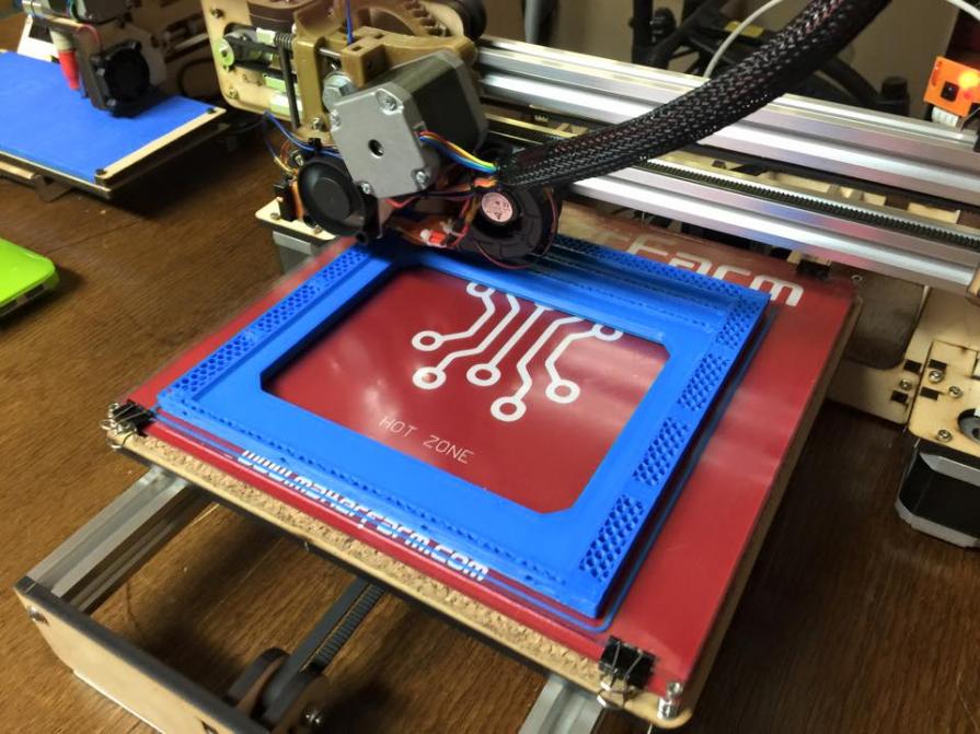
The first print off the machine, 195x195x12mm, PLA, with a 20% infill. The rigidity of this piece is incredible, on par with the wood frame of the printer itself.
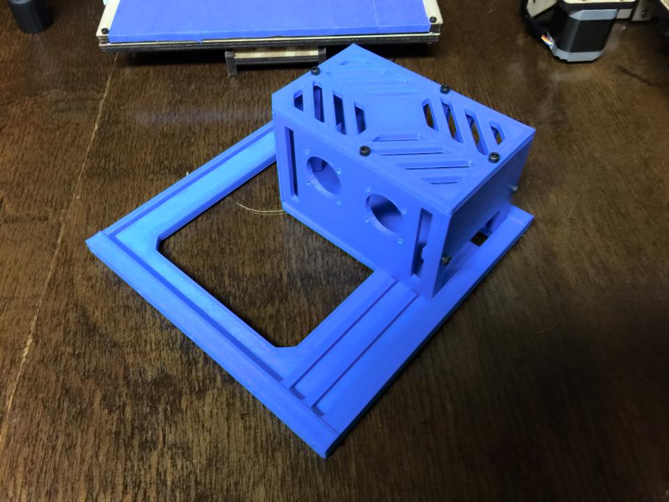
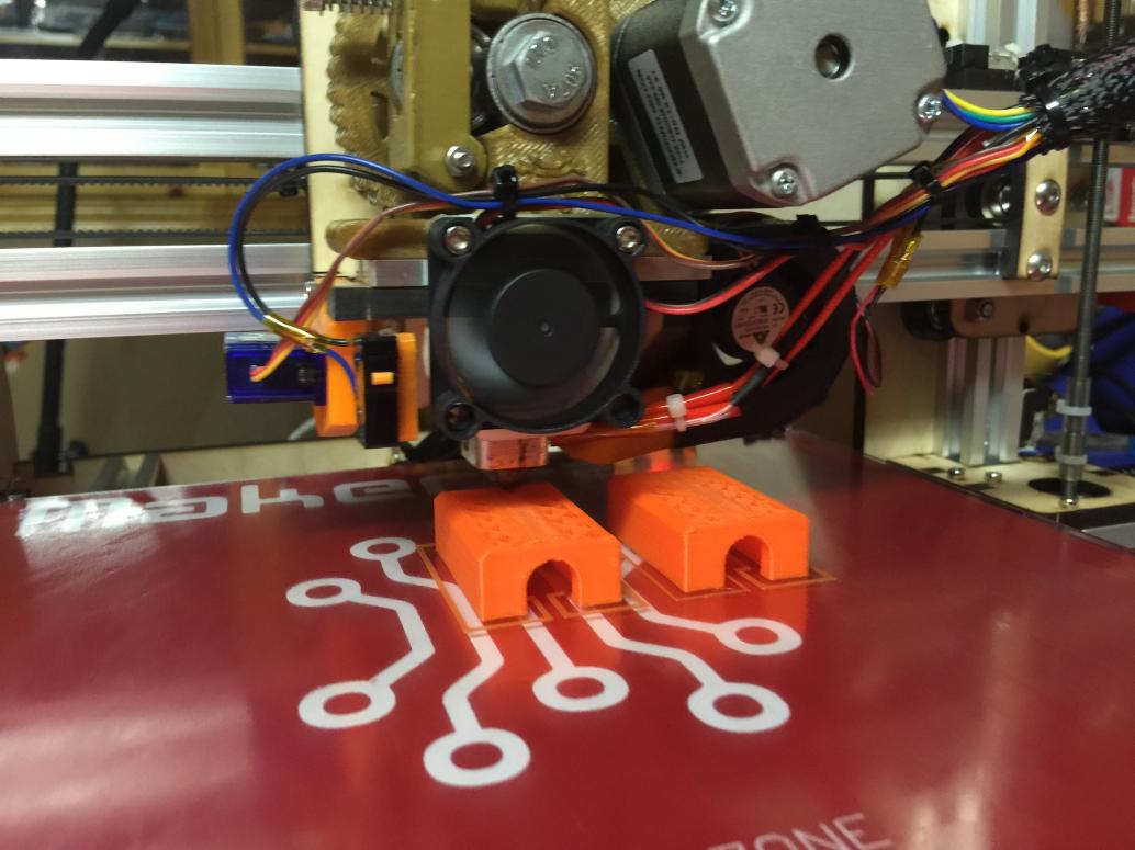
The rear frame panel with the electronics enclosure to check for fitment and alignment. Dual 20mm fan mounts to provide for extra cooling if needed.
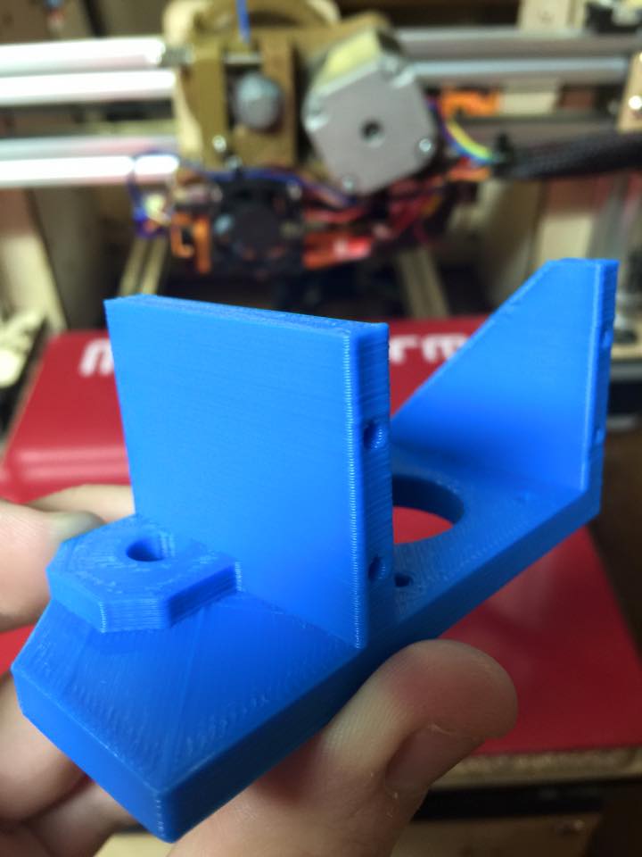
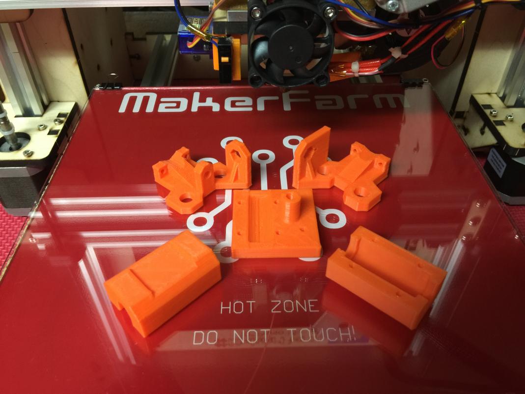
One of the motor mounts, printed at 75mm/sec, the walls and details seem to have come out fairly well. Overall, happy with the quality of prints it's been producing
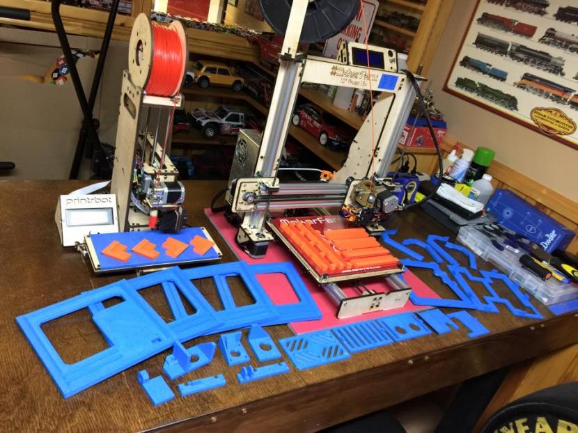
Lastly, every print that's been turned out in the last 2 weeks. To date, 33 prints, with another 25 or so remaining! Let the fun begin!
Cheers
RyanLast edited by MiniMadRyan; 02-05-2015 at 06:10 AM.
-
01-21-2015, 06:22 AM #2Engineer-in-Training
- Join Date
- Jul 2014
- Location
- Ontario, Canada
- Posts
- 257
Well, thought I'd throw up a render of the hopeful final product.
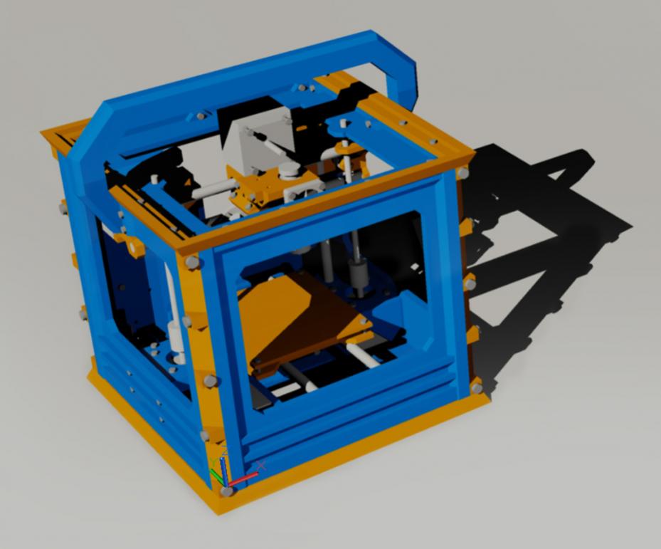
The printer was designed over the holidays, with the intention of having most every part, frame included, being 3d printed. My goal was also to make the printer printable by anyone with a printer capable of an 200mm x 200mm build volume. As such, the overall foot print of the printer is about 215mm x 215mm x 240mm, or roughly big enough to fit on a standard piece of paper.
The printer uses a fairly standard set up, similar to a Prusa, with the extruder moving in the X and Z axis, and the bed in the Y axis. Build volume is on the smaller side, at about 100x100x100, but given the size of the printer, I felt this was a good accomplishment.
There's a rearward facing electronics housing, which, while protruding from the rear, provides ample room for the electronics and room to tinker. RAMPS 1.4 will drive the printer, and an external laptop style PSU will be used.
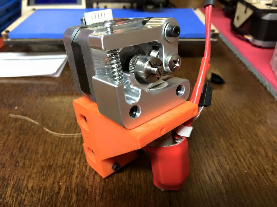
Extruder wise, I've decided to use a Printrbot aluminum extruder, and a Ubis hot end, as these were left overs in the workshop, however the extruder mount has been designed to also accept Hexagon and E3D hot ends as well.
Otherwise, the printer has the usual array of linear rods and bearings, GT2 pulleys and belts, and Nema17 motors. It's my goal, that after building the first printer and validating that it works, to release the CAD drawings, STLs, build instructions and whatever else under the open hardware guidelines for anyone else to use and modify.
Cheers
RyanLast edited by MiniMadRyan; 02-05-2015 at 06:11 AM.
-
01-23-2015, 08:09 AM #3Engineer-in-Training
- Join Date
- Jul 2014
- Location
- Ontario, Canada
- Posts
- 257
The latest prints off the printer last night. These represent the linear rod mounts for the X axis, and the bearing holders for the Y axis. I've redesigned the rod mounts ever so slightly to add some additional strength around the screw points.
With these printed, there remains about a dozen parts left, most of them motor mounts, the build platform, and various other bearing holders and misc parts. Waiting on hardware to arrive this week as well.Last edited by MiniMadRyan; 02-05-2015 at 06:12 AM.
-
02-05-2015, 06:30 AM #4Engineer-in-Training
- Join Date
- Jul 2014
- Location
- Ontario, Canada
- Posts
- 257
Well after a short delay waiting on the mechanical components to arrive, and revising a few parts here and there, we're finally onto the build!
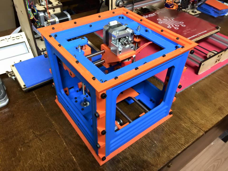
The frame went together well with very few issues, although it was a more prolonged build thanks to the multitude of screws and tight spots. Overall though, the frame went together well, and is superbly strong. The inside corner brackets, combined with the outer corners, and top and bottom frames, make the entire frame rock solid, and as heavy as a rock too. Given that the bulk of the printer is plastic and screws, it's amazing how much the entire unit weighs!.
The linear rods, bearings and other little bits have arrived, so tonight will hopefully see most of the printer completed!
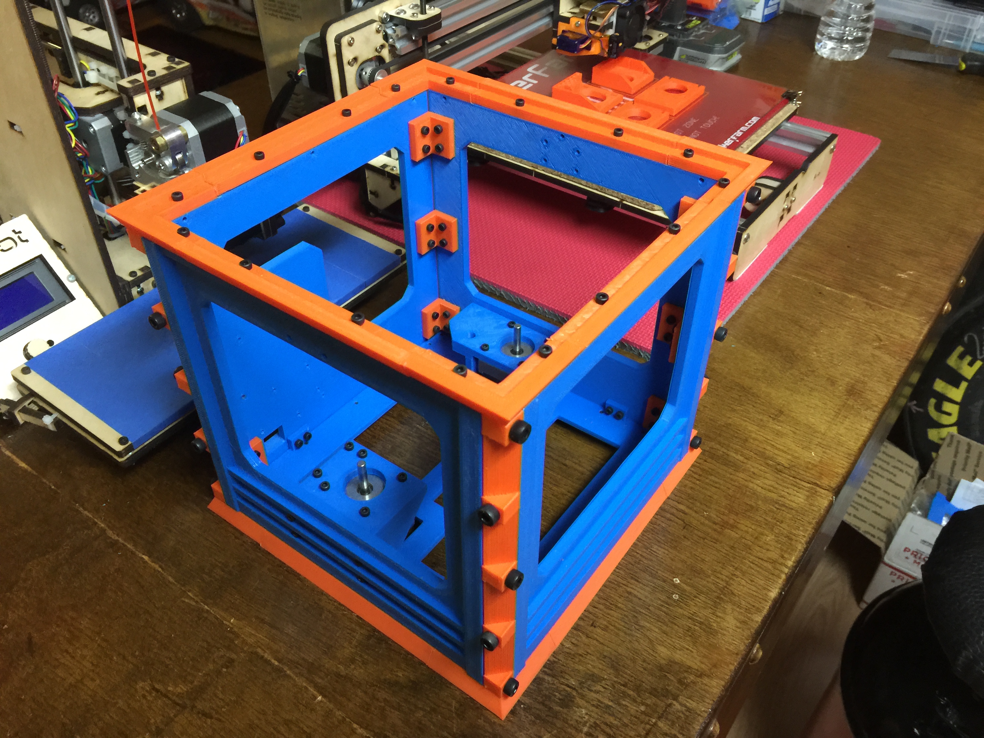
The top side of the frame
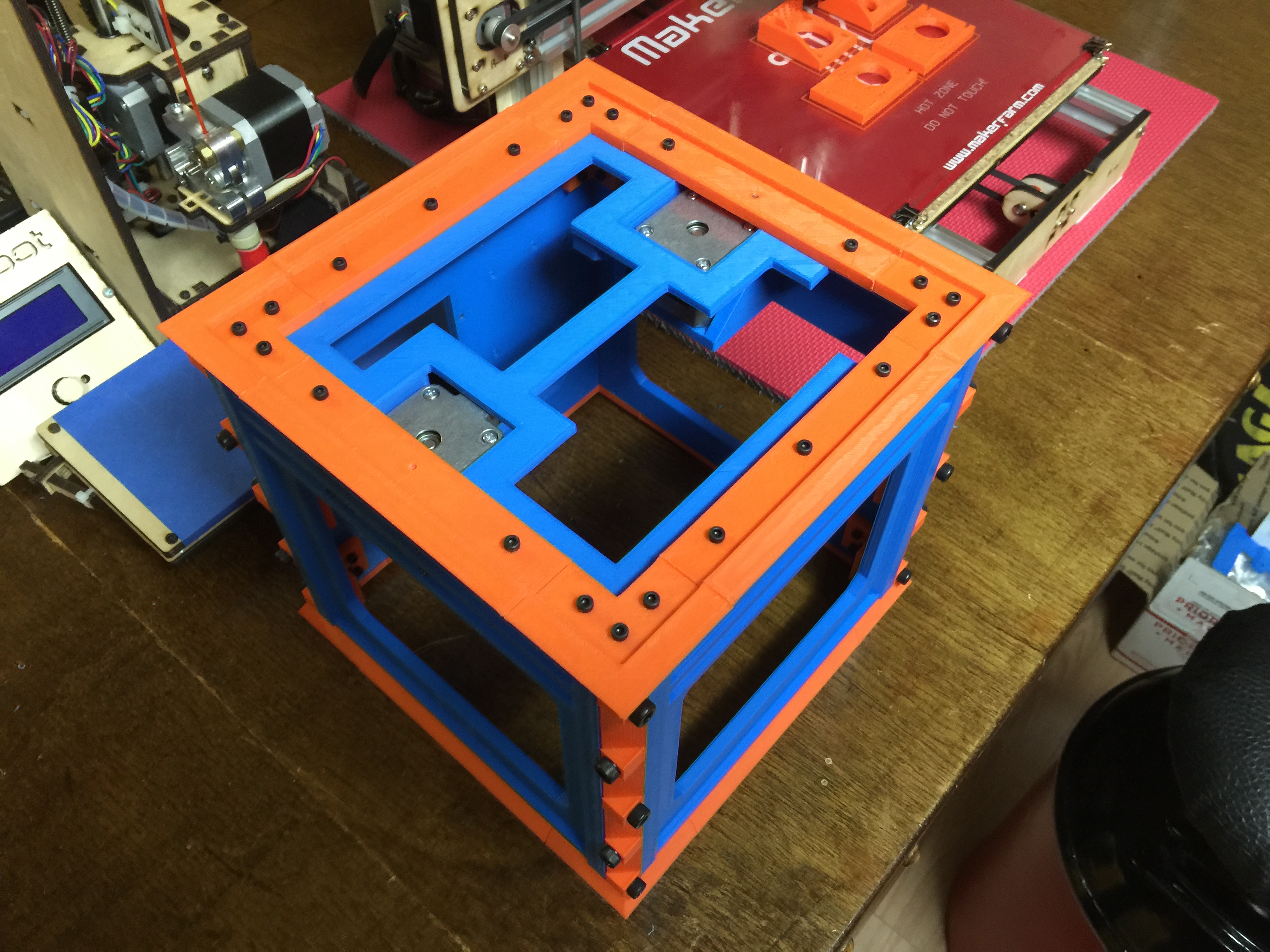
The bottom side showing the lower frame/feet for the printer and the bottom inner frame
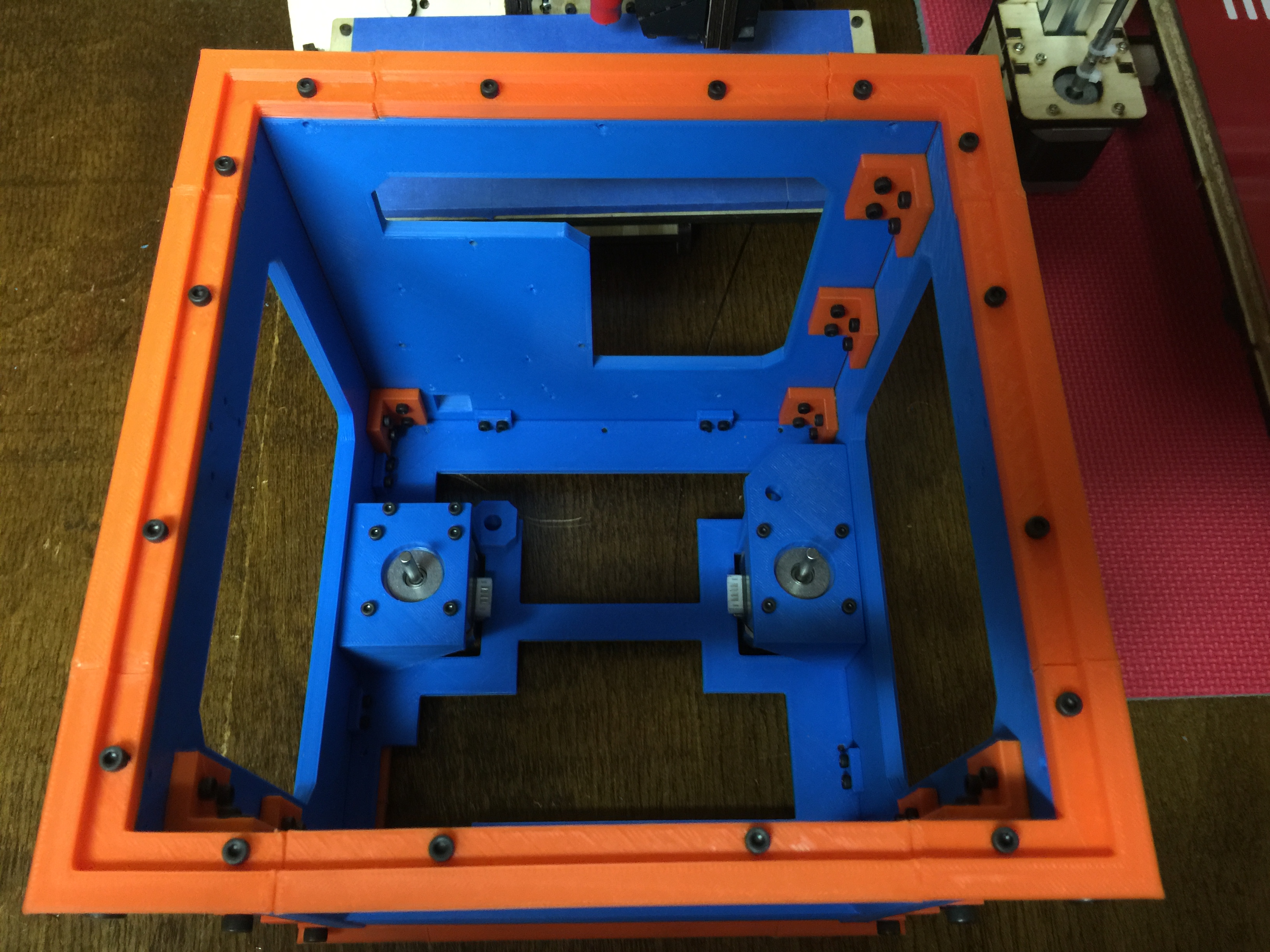
The inside of the frame, inner corner brackets, and Y motors in place
Ryan
-
02-11-2015, 05:35 AM #5Engineer-in-Training
- Join Date
- Jul 2014
- Location
- Ontario, Canada
- Posts
- 257
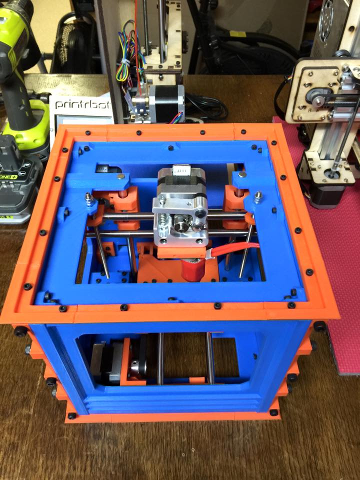
It's that time again! There's been some good progress made this week. The extruder and bearing holders were put together without issue, and yesterday marked the installation of the linear rods into their respective homes. So far, the build has progressed well with little modifications needed, however I will be redesigning the extruder carrier slightly to make the GT2 belt installation easier.
Cheers
Ryan
-
02-11-2015, 06:35 AM #6Super Moderator
- Join Date
- Jul 2014
- Posts
- 8,818
wow !
Well impressed.
Closest thing to an actual reprap I've yet seen.
So why did you go for an all metal extruder rather than a printed one ?
And what's the overall cost of the metal/electronics parts someone would need to buy ? (assuming they didn'thave them lying around their workshop :-)
-
02-11-2015, 07:00 AM #7Engineer-in-Training
- Join Date
- Jul 2014
- Location
- Ontario, Canada
- Posts
- 257
Thanks curious aardvark! Originally Posted by curious aardvark

The extruder choice was purely down to what I had laying around the workspace, and was also the smallest of the extruders I'm familiar with. I may try for a printed direct drive extruder in the future though.
The overall costs I've tried to keep to a minimum. The purchased components include electronics, pulleys and belts, stepper motors, bearings and linear rod. My total cost so far has been right around $250 for everything, though I could have gotten it down to around $200 had I been more selective and wasn't so impatient! (and about a Kg of material used!)
The downside of the entire build was the print time, the frames taking 4-5 hours each. There's about 60 hours of printing here. I've thought about re-designing the printer to use OpenBeam/V-Slot for the frame to cut the printed parts time down to a day or less
Ryan
-
02-23-2015, 05:40 AM #8Engineer-in-Training
- Join Date
- Jul 2014
- Location
- Ontario, Canada
- Posts
- 257
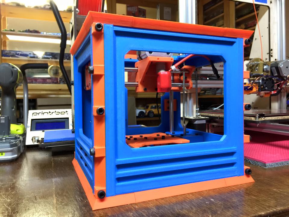
Well after a week or so of tweaking and other projects on the go, I present to you, the finished printer.
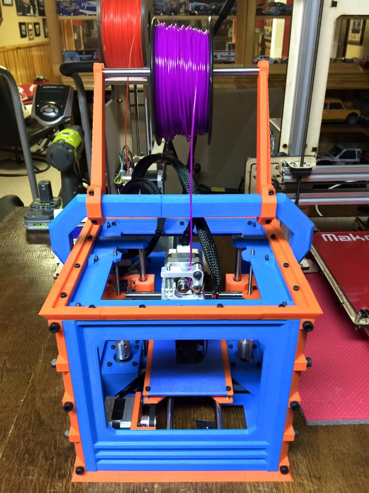
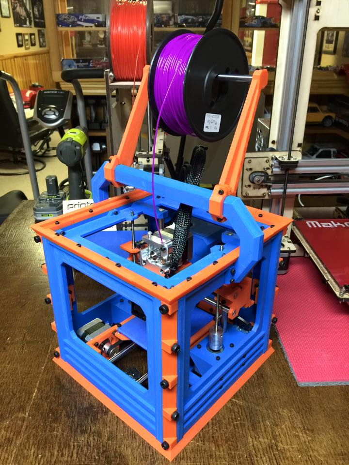
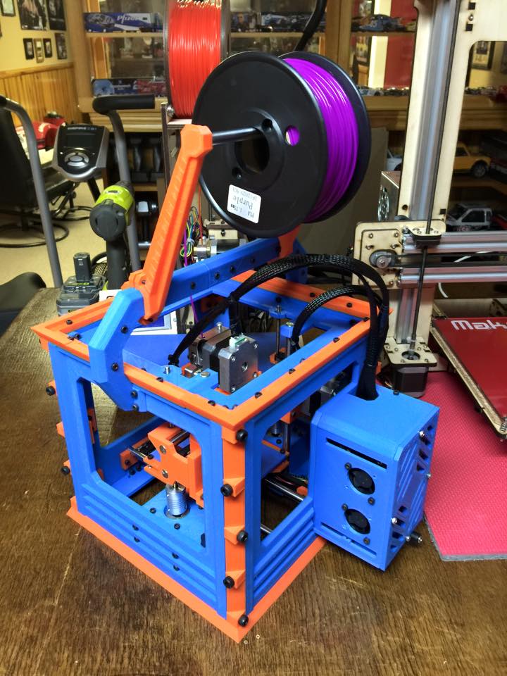
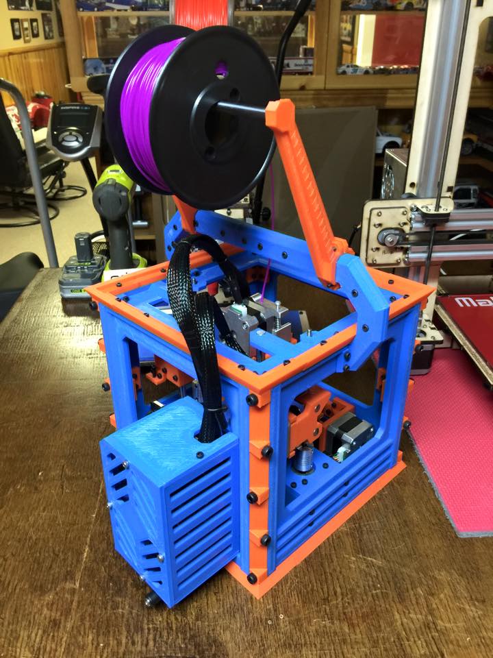
I'm fairly pleased with the final outcome and functionality of the printer itself. There was initially some concern over heat and softening plastic being an issue, but after several calibration prints, it hasn't been an issue. The overall build volume is just under 4" cubed. I will be releasing the original drawings and STL's for the printer in the next while for anyone who wishes to print their own or have a look at its design. I've already started planning on the next generation of this printer, and to hopefully offer it to the public in the next while
Cheers
Ryan
-
02-26-2015, 09:49 AM #9Administrator
- Join Date
- Jan 2014
- Posts
- 7,697

Members of the 3DPB.com community are impressive innovators and makers, and user MiniMadRyan has been updating us over the last month about his 3D printed 3D printer project. This very sturdy RepRap 3D printer utilizes four 3D printed side frame panels that house the build platform. Ryan notes that he will be releasing original drawings and STL files for anyone who would be interested in trying their hand at his design. The 3D printer requires 58 3D printed parts and about $250 worth of materials that can't be 3D printer. Find out more about the project: http://3dprint.com/46657/3dpb-forum-member-3d-printer/
-
02-26-2015, 08:33 PM #10Engineer-in-Training
- Join Date
- Jul 2014
- Location
- Ontario, Canada
- Posts
- 257
Thanks Brian for an amazing write up! It was truly the highlight of my day to see your article on 3DPrint.com!
As promised, I've cobbled together the sources for the printer and published them for all to see, print, build and tweak! I haven't had time to finish a complete build guide yet (it's coming!) or a detailed write up, but I think there is enough information for anyone to build the printer as is. If there's any questions, comments or concerns, or if anyone sees anything that should be fixed, just let me know, and I'll see what I can do!
Download: https://www.youmagine.com/designs/ma...ini-3d-printer
Anyways, I hope everyone enjoys the printer and it's design. I'll hopefully be able to share v2.0 and a few other surprises in the near future!
Ryan

 Reply With Quote


Do bed magnets deteriorate.
04-29-2024, 01:35 AM in General 3D Printing Discussion