


Results 1 to 5 of 5
-
07-20-2021, 02:22 PM #1Banned

- Join Date
- Mar 2021
- Posts
- 62
How S6 V 2,0 Bord 32 connect TFT43 V3.0?
Hello.
Please I want to replace the motherboard with S6 V 2.0 Bord 32 Bit, TMC2226 V 1.0 UART drivers and BTT TFT43 V3.0 display on the Ender 5 plus. How do I connect the board to the display?
Thank you in advance for your help.
-
07-20-2021, 04:58 PM #2Staff Engineer
- Join Date
- Jul 2016
- Location
- South Florida, USA
- Posts
- 1,248

Good evening. There are 2 seperate connections that need to be made for the dual mode display to work in both modes. The first connection is the 2 ribbons that run to the exp1 and exp2 headers. This will let the screen function as a lcd12864 display using the knob for input. The other half is 4 or 5 pins. the minimum 4 pins needed are +5v, ground, rx, and tx. The fifth pin would go to a reset pin if we can find one on that board. When this pin gets grounded it triggers the mainboard resetting when we hit reset from the screen. So it is nice but not needed. And with this connection made the display can work as a color touchscreen. I have not had the pleasure of playing with one of these boards personally so I will get you as far as I can and then you can take it from there. Here is the backside of your mainboard with all the pins labeled. We care about the red and yellow circles..
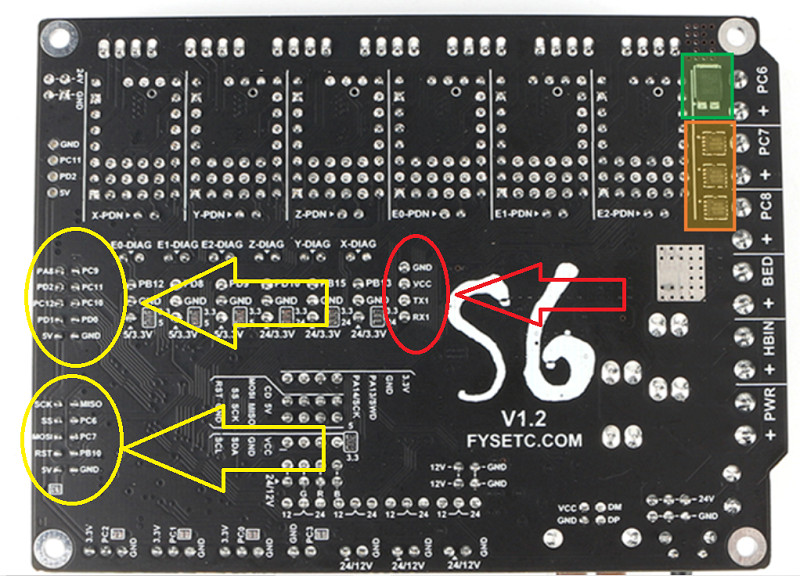
It is nice how the pins are all labeled on the backside of the mainboard, no? So you will use rx1 and tx1 as your communication lines for the TFT. But beware the power pin is just labeled vcc and not +5v. I would probe that pin first when powered up and just make sure it is not 3.3v or 12v or 24v. Just to be safe. And sometimes rx from one device needs to be wired to tx on the other and vice versa so if you cant find the joy swap the rx and tx pins and retry.
Because the tft mode is not hard wired and communicates with the board over a uart communication The board has to be powered up before the tft will communicate. Just like connecting to a usb. So give it a minute after power on to start showing you those temp sensor values. To help as much as I can here is a picture of the front side of the mainboard with the headers circled..
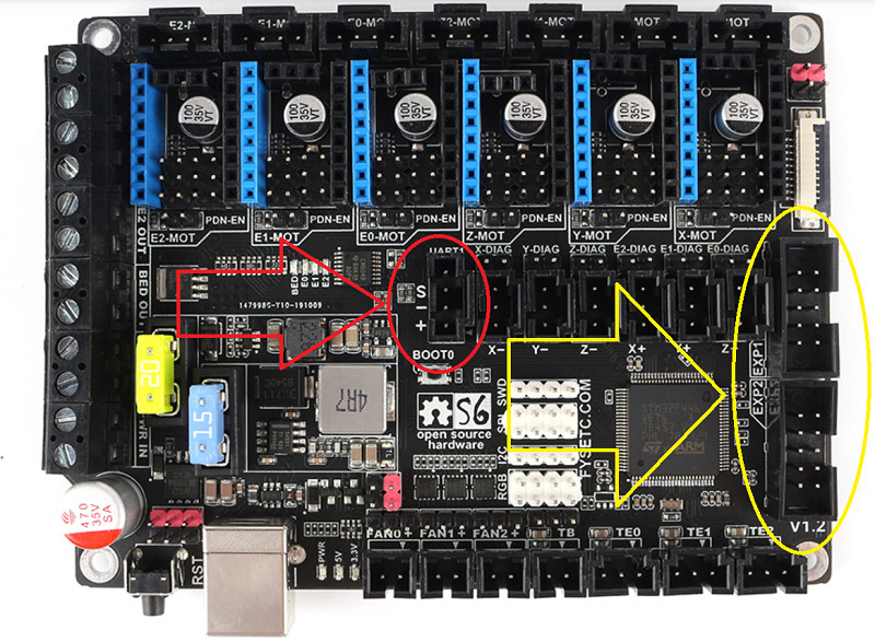
Don't forget to make sure you are only sending 5v to the screen.
-
07-21-2021, 06:32 AM #3Banned
- Join Date
- Mar 2021
- Posts
- 62
Hello.
Please, since I'm just learning everything, which pin should I connect the VCC to to find out what power supply it has?
Thank you for your help.
-
07-21-2021, 12:09 PM #4Staff Engineer
- Join Date
- Jul 2016
- Location
- South Florida, USA
- Posts
- 1,248
You should use a digital volt and ohm meter or DVOM to probe the vcc and gnd pins and verify the display on the DVOM shows 5v when the board is powered on. That is the best way to verify voltage. If the vcc pin shows 12 or 24v then you will need to find a pin on the mainboard labeled 5v and connect the power to that pin.
-
07-21-2021, 01:26 PM #5Banned
- Join Date
- Mar 2021
- Posts
- 62
Thank you for your great help.

 Reply With Quote


Extruder not feeding during print,...
04-24-2024, 01:59 AM in Tips, Tricks and Tech Help