


Results 1 to 9 of 9
-
02-04-2015, 05:58 PM #1Staff Engineer

- Join Date
- May 2014
- Location
- Highlands Ranch, Colorado USA
- Posts
- 1,437

Comparison of Type 1 thermistor and E3D thermocouple temperature measurements
This sort of builds on the Marlin temperature measurement information provided in thread Comparison of Type 1 and Type 6 thermistortables.h data.
Another way Marlin can perform temperature measurements is through use of a thermocouple. Thermocouples function through a temperature-dependent low-level voltage being generated in a junction of two dissimilar metals. Various thermocouple amplifier breakout boards are on the market that simplify interfacing a thermocouple to something like RAMPS and the MEGA2560 board. Differences include aspects like the type of thermocouple(s) supported, the chip used, and the nature of the output interface. The most common kind of thermocouple is Type K, which uses a junction of chromel and alumel.
My reading suggested that given a circuit with the means of calibrating to specific parts, thermistors can typically measure more accurately than thermocouples. Unfortunately, neither RAMPS hardware or Marlin firmware provides for part specific calibration. Thermocouples are reported to read more consistently in situations without calibration to a specific thermocouple part.
For the easiest integration with existing thermocouple support built into Marlin, I purchased the E3D thermocouple amp and E3D Type K thermocouple from Filastruder to experiment with. The AD597 chip and thermocouple should provide a measurement accuracy within 5 or 6 degrees C. This thread provides comparison measurements between the E3D thermocouple and my original MakerFarm thermistor configured as a Type 1 thermistor in Marlin.
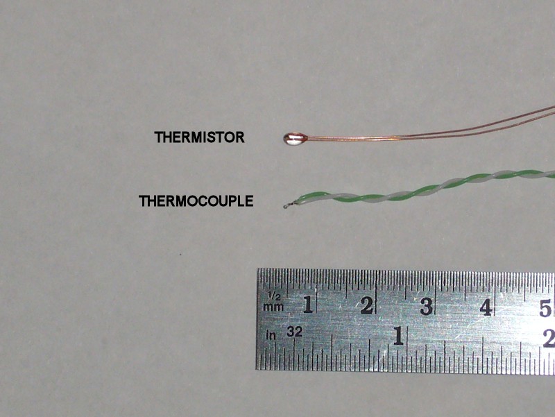
For a physical comparison, the welded connection of the thermocouple is very small.
TEST SETUP
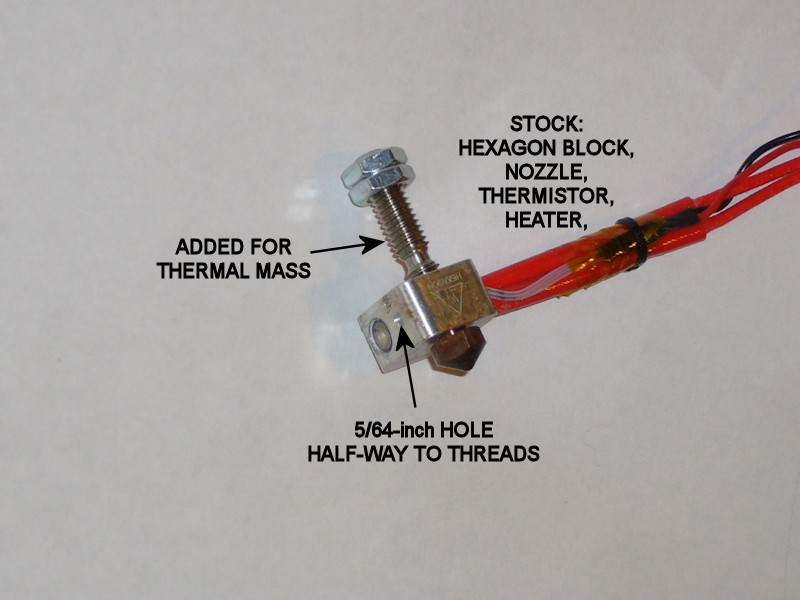
Stock parts from the MakerFarm kit that were used include the aluminum block, 0.40mm nozzle, and cartridge heater from a hexagon hot end, and the MakerFarm thermistor bonded to the aluminum block with a small dab of Permatex Muffler & Tailpipe Sealer. The sealer was applied when I originally built the printer last year, so it is well cured at this point. For additional thermal mass, a different type of barrel was added to the aluminum block and tightened to the nozzle.
A 5/64-inch hole was drilled into the aluminum block on the side opposite from the thermistor hole. Depth of the hole was to about the mid-point of the aluminum between the exposed side of the block and the threaded hole.
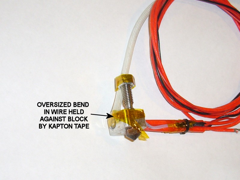
I didn't use the muffler sealer on the thermocouple due to the need to let it cure and the fact that it seems to form a permanent bond; I wanted to reuse the thermocouple after this testing was complete. The thermocouple leads were bent so that after the thermocouple was inserted into the new hole, the bent leads would NOT be flush with the aluminum block. A small wad of kapton tape was pressed into the hole with the thermocouple to help push thermocouple joint against the side of the hole and kapton tape was used to provide some pressure on the bent leads as a means of pushing the thermocouple into the hole. Some fiberglass sleeving was used to protect the thermocouple wiring, although the wiring is insulated with PTFE.
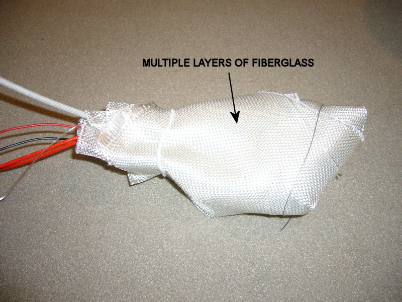
The completed block assembly was then wrapped in several layers of automotive repair type fiberglass mesh to form a controlled environment for the thermal mass. The wrapped assembly was then tucked into a large Styrofoam soft drink cup for even more thermal isolation from the ambient environment. Leads left the Styrofoam cup through the enlarged straw hole in the cup lid.
RAMPS CONNECTIONS AND MARLIN MODIFICATIONS
Information on connections and Marlin modifications is available at http://reprap.org/wiki/ExtThermoCouple_1.0.
As described in the link, Marlin was configured to use the thermocouple input as the hot end temperature sensor. For a temperature comparison, the thermistor was connected to RAMPS as the heated bed sensor, and the configuration.h BED_MAXTEMP temporarily raised to 291 degrees.
The thermocouples are essentially polarized. To get the measured temperature increasing with increased actual temperature, I found I had to reverse the thermocouple connections at the thermocouple amplifier from what is shown in the wiki.
TEST METHOD
The Marlin hot end temperature control loop was used for the test. I made no attempt to recalibrate the control loop PID parameters for this standalone hot end assembly. Simplify3D was used as the host software. Temperatures were monitored on the communication pane in the S3D machine control panel. In verbose mode, this allowed 15 measurements encompassing about 30 seconds to be displayed with the S3D full-size on the available display.
New temperature settings were allowed to soak for a minimum of 5 minutes before capturing measurement data. When collecting data, Simplify3D verbose mode was disabled to stop the communication pane from scrolling so data from the last 15 measurements for both the thermocouple and thermistor could be recorded. The 15 tenth-degree measurement samples were then averaged in Excel for use as a composite result for each sensor. I'd include a graph of the data, but Office 2010 has made creating charts in Excel much more of a pain than it used to be.
TEST RESULTS
The PDF file in the thermocouple_test.zip file contains a table showing measurement results from 25 degrees C to 255 degrees C. 255 degrees became the upper limit of the test when the thermistor readings exceeded the revised limit for BED_MAXTEMP and Marlin shut off the heater. Remember that this data is based on a sample of one thermocouple and one thermistor.
The thermistor data indicated a significant change in linearity at the 255 degree test point. Testing was repeated at the 250 and 255 degree set points with consistent results.
POST-TEST OBSERVATIONS AND ERROR ANALYSIS
No calibrated thermometer or temperature source was available as an independent reference in the test.
In case others run across it, I didn't save the link, but one blog or thread suggested a 10uF capacitor needs to be added to the ATMEGA ADC input pin in order to reliably measure thermocouple inputs. I don't recall what thermocouple amp board was being addressed in that blog or thread, but I did try adding the capacitor for some preliminary tests and observed no change in data. The wiki schematic for the E3D thermocouple board does show a capacitor on the amplifier output that may suffice for whatever filtering that blog or thread was referencing.
A note on measurement averaging - At least two levels of data averaging is applied here. I averaged the data from 15 consecutive temperature readings read from the printer by Simplify3D. I now better understand how Marlin goes about temperature measurements - it turns out that every temperature determination in Marlin is actually a composite of 16 measurement samplings. It is possible/likely that not every temperature determination in Marlin is read by the host computer. I don't think this averaging affects the quality of the test - just describing it in case anyone wonders about the extent averaging was performed.
Both the thermistor and thermocouple approaches have errors in the temperature measurement process. Errors in the thermistor measurement were discussed in the Comparison of Type 1 and Type 6 thermistortables.h data thread. To summarize, errors are predominantly going to be caused by the tolerance of the 4.7K resistor used as the pull-up portion of the voltage divider formed with the thermistor, and the tolerance of the thermistor itself.
Obvious error sources with the thermocouple approach include the accuracy of the thermocouple and the accuracy of the thermocouple amplifier. The thermocouple spec sheet linked to at Filastruder shows a thermocouple accuracy of +/- 1.5 degrees C. The AD595 pretty much sets the standard for the thermocouple amp genre, with some grades good to a +/- 1 degree C calibration spec. Unfortunately, I didn't realize until I prepared for the tests that the E3D board actually uses an AD597, a lesser chip laser-calibrated to a spec of +/- 4 degrees. There's an additional temperature linearity spec, but I don't think it applies since it assumes the amp chip will be exposed to varying temperatures along with the thermocouple. That wouldn't be the case for our printer applications. So, I think a "base error" begins with the +/- calibration spec of the AD597. The AD597 sill stay at a fairly constant temperature, so I believe the additional error over a temperature range may likely be the +/- 1.5 degrees of the thermocouple. The thermistor likely won't be that accurate without part-specific calibration.
There is, however, another significant error source for AD595/AD597 type thermocouple measurements using the Arduino-type MEGA2560 boards. The AD595/AD597 outputs an analog voltage (10 mV per degree C) that Marlin samples with the analog-to-digital converter (ADC) inside the ATMEGA2560 processor. The analog output of the AD595/AD597 is essentially unaffected by the absolute voltage of the +5V supply powering it. Unfortunately, Marlin configures the ATMEGA2560 processor to use the board VCC as the full-scale input reference for the ADC. Since it would nominally be 5.0V, this is the full-scale value assumed in temperature measurement calculations performed in Marlin. So, the accuracy of the ADC measurements depends on the accuracy of the 5V supply on the MEGA2560 board. In my case, I now see that operating the printer electronics off a 5V wall-wart as part of my recent power "improvements" set the board VCC to 5.3V. Looking at the Marlin code, this likely caused the thermocouple measurements in my test to read low (and thus the thermal mass temperature to be set high) by 6%. At a temperature of 200 degrees, this would be an error of about 12 degrees - a significant portion of the diverging error shown between the thermocouple data and the thermistor data.
The thermistor analog measurements don't have this same error component since the voltage divider formed with the thermistor is also sourced by the same 5V supply as the reference for the MEGA2560 ADC. Any error in VCC would affect both equally.
PLANS FORWARD AND RECOMMENDATIONS
The test will be repeated after the VCC discrepancy on my printer is resolved. This could be accomplished by changing the full-scale value in the Marlin measurement calculations, but that isn't a good permanent solution since the voltage from my wall adapter could change or drift.
Unless one can ensure the 5V source on their MEGA2560 is rock steady at exactly 5.0V and stays that way regardless of whether the MEGA2560 is powered from USB vs. the printer 12V supply, I don't recommend using a thermocouple board based on the AD595 or AD597. Likewise, without that precise VCC source I wouldn't recommend any other mod or improvement that relies on the ADC measurement capability of the MEGA2560 processor without analyzing the effects of the error caused by using the board VCC as the full-scale reference.
There are other thermocouple boards (from Sparkfun, Adafruit, etc.) that leverage other parts using an SPI digital interface. They would likely sidestep the issue with stability or accuracy of the 5V source. Marlin has some built-in support for them as well (via the MAX6675 type). The MAX6675 is actually an obsolete part; research needs to be performed to determine whether newer parts are compatible with the Marlin support for the MAX6675.
FOLLOWUP COMMENT: For the MakerFarm i3v printers with RAMPS electronics and a RepRapDiscount smartpanel with LCD and SD card, there's an additional concern to be resolved in using the MAX6675 type boards with SPI. Marlin also interfaces with the SD card through SPI. While SPI is addressable and supports multiple devices being on the bus, the ATMEGA2560 hardware function for the SPI interface is connected to pins on the RAMPS AUX-3 connector. The RepRapDiscount LCD adapter plugs onto AUX-3 and AUX-4, limiting access to the SPI hardware pins (SCK, MISO, MOSI) by another device. One might be able to extend the AUX-3 pin connections to the MAX6675 board, but that would still leave open whether there's risk of using the SPI bus for both SD card access and the temperature measuring board. I haven't dug into the extent Arduino supports it, but it might also be possible to move one of the SPI devices to a software-based SPI on pins available elsewhere on RAMPS. That, however, carries risk with the increased processor loading of handling the SPI handshaking in software.Last edited by printbus; 05-02-2015 at 09:40 PM. Reason: migrated to offsite attachment storage due to 3DPrintBoard issues
-
02-04-2015, 06:12 PM #2Engineer
- Join Date
- Nov 2014
- Posts
- 522
basically what you are saying is thermistors aren't accurate... or at least compared to thermocouples...
I'm interested in your thoughts on this, but to me it seems like replacing thermistors with thermocouples "should" in theory produce better prints and alow for more fine tuning of print quality via heat.
-
02-04-2015, 06:51 PM #3Engineer-in-Training
- Join Date
- Feb 2014
- Location
- CT
- Posts
- 345
I have a calibrated meter i can run some tests.
-
02-05-2015, 08:20 AM #4Staff Engineer
- Join Date
- May 2014
- Location
- Highlands Ranch, Colorado USA
- Posts
- 1,437
Back to the drawing board. The data presented in the original post is flawed and pretty much useless.
Overnight, I realized the AD595/AD597 thermocouple measurement approach has an error component that the thermistor approach wouldn't have. This morning, I determined the error on my printer would cause the thermocouple measurement readings to be low by about 6%, or about 15 degrees at a setpoint of 250 degrees. That goes a LONG ways to explaining the discrepancy between the thermocouple and thermistor measurements.
The original post has been expanded with an interpretation of the test data that discusses this new found issue. I'll have to repeat the entire test, and I'll have to see when I can block the bank of time aside for it. Throughout the hours it takes to do the test, I'll be reminded how I'm not so enamored with AD595/AD597 temperature measurements using the MEGA2560 board.Last edited by printbus; 02-05-2015 at 03:11 PM.
-
02-05-2015, 02:26 PM #5Student
- Join Date
- Sep 2014
- Posts
- 4
"I'm hoping someone who can professionally speak to the thermistor-vs-thermocouple debate responds."
Well, I'm not sure how professionally I can speak, but I do design temperature measurement systems for NASA.
-
02-05-2015, 02:31 PM #6Staff Engineer
- Join Date
- May 2014
- Location
- Highlands Ranch, Colorado USA
- Posts
- 1,437
OK - good to know. Stand by. I'm in the process of revamping the thread contents. The test will need to be repeated. Originally Posted by rco3

-
02-05-2015, 02:39 PM #7Engineer-in-Training
- Join Date
- Jul 2014
- Posts
- 204
I'll tell you this, the K type thermocouple that came with my $50 multimeter is either wildly inaccurate, out of calibration, hard to use properly, or all three.
I'm not surprised that the thermistor reads ~8% higher than advertised, this fits exactly with IR thermometer readings i've taken.
-
02-05-2015, 03:13 PM #8Staff Engineer
- Join Date
- May 2014
- Location
- Highlands Ranch, Colorado USA
- Posts
- 1,437
That's good to know, too. Originally Posted by TopJimmyCooks
I have an IR thermometer too, but I haven't bothered to apply it here. I think they're also generally not very accurate, and I'm not sure that measuring the surface temperature of an exposed hot end is a good representation of the temperatures inside the heat reservoir block.I'm not surprised that the thermistor reads ~8% higher than advertised, this fits exactly with IR thermometer readings i've taken.Last edited by printbus; 02-07-2015 at 07:15 AM.
-
02-07-2015, 07:56 AM #9Staff Engineer
- Join Date
- May 2014
- Location
- Highlands Ranch, Colorado USA
- Posts
- 1,437
REVISED COMPARISON TEST RESULTS
The original post has been updated to explain the issue of an imprecise source of supply voltage for the MEGA2560 board affecting the analog-to-digital converter (ADC) measurements of AD597-type thermocouple amp board output. Marlin configures the ATMEGA2560 processor ADC to use the board VCC as the full-scale reference for the ADC. The AD595/AD597 type thermocouple parts output an analog voltage that is scaled to the temperature present at the thermocouple. Those parts, as do most analog parts, strive for a stable output regardless of variations on their supply voltage. So, use of an imprecise source for 5V power on the MEGA2560 board can, and did in my case, add a substantial error into the ADC measurements.
While not a permanent solution, I set the printer up to use a regulated power supply set to 5.00V as the 5V source for the MEGA2560 and reran the thermocouple-thermistor comparison test. I have diode D1 removed on the RAMPS board, which prevents the MEGA2560 on-board regulator from providing 5V derived from the printer 12V power. I also disable the +5/VCC line in the USB cable from my host computer, eliminating USB as a possible 5V source for the board.
TEST SETUP
Except as noted, the test setup is the same as in the original test. The kapton-wrapped assembly of the thermal mass, heater, thermocouple and thermistor was still intact from the prior test. I did have to rewrap the assembly in the fiberglass mesh.
A Fluke 77 multimeter (0.3% accuracy spec, but uncalibrated) was added to the test setup to independently measure the analog output voltage of the E3D thermocouple board at each setpoint. At a scaled output of 10mVDC per degree C, it can be used to validate the accuracy of ATMEGA2560 ADC measurements and the Marlin interpretation of them.
TEST RESULTS
An updated table of test results is available in this zipped PDF file.
The results show a reasonable track between the scaled analog output of the E3D thermocouple board and the thermocouple temperatures provided by Marlin. This somewhat validates that the analog temperature signal is now being correctly measured by the ATMEGA2560 ADC.
The temperatures reported by the thermocouple and thermistor still diverge with increased temperature, but at a lesser extent than they did in the original test. All the test was intended to do was compare the measurement data. The test configuration did have access to a calibrated measurement reference that could be used to independently prove which approach was more accurate.
As stated in the updated original post, based on the new-found concern over accuracy of the ATMEGA2560 processor supply voltage, I do not recommend the use of an AD595/AD597 type thermocouple amp board. I would also discourage any other printer mod that requires an independently sourced analog voltage to be sampled by the ATMEGA2560 ADC and the existing Marlin firmware without understanding the error that the processor VCC can contribute.Last edited by printbus; 05-02-2015 at 08:47 PM. Reason: migrated to offsite attachment storage due to 3DPrintBoard issues


 Reply With Quote


Extruder not feeding during print,...
04-28-2024, 02:02 PM in Tips, Tricks and Tech Help