


Results 1 to 10 of 12
Threaded View


-
09-23-2014, 12:27 PM #1Staff Engineer

- Join Date
- May 2014
- Location
- Highlands Ranch, Colorado USA
- Posts
- 1,437

Comparison of Type 1 and Type 6 thermistortables.h data
Multiple threads have been discussing the details of temperature measurements in the Marlin firmware. Most recently, this has been in thread Auto Bed Leveling troubles. This thread is an attempt at sharing what I've learned in researching the temperature measurements. Smartphone readers are forewarned that this is a lengthy post.
NOTE: This is discussing Marlin file contents current as of mid-September 2014
BACKGROUND
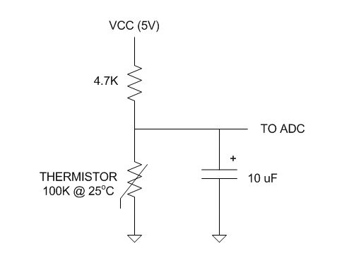
For our MakerFarm printers, thermistors are used to sense temperatures at the hot end nozzle and heated bed. These are devices that change resistance with temperature. In the reprap world, the thermistors are used in a voltage divider network with a fixed resistor (typically 4700 ohms) going to VCC (5v) and the thermistor going to ground. The voltage observed at the junction of the two will vary with temperature following resistive voltage divider math. In Marlin/RAMPS, this voltage is measured using the 10-bit Analog-to-Digital Converter (ADC) in the Arduino Mega microcontroller. A decoupling capacitor is added to help filter low-frequency noise from the voltage being measured. Here's a summary diagram; this is repeated for each thermistor. There's only one ADC in the microcontroller, but it also has an analog switch that allows different inputs to be selected for measurement.
Due the properties of the materials involved, thermistors are very non-linear. To simplify the firmware effort necessary to determine a temperature from the measured voltage across the thermistor, lookup tables are used that correlate ADC measurement values to predetermined temperatures.
In Marlin, source file thermistortables.h contains the lookup tables for various thermistors and measurement schemes. In configuration.h, constant TEMP_SENSOR_BED is defined to specify which of the lookup tables should be used with the thermistor on the heated bed. Constant TEMP_SENSOR_0 specifies which of the lookup tables should be used with the thermistor on the primary hot end.
Confusion and issues in all this surfaces in multiple ways -
- Our thermistors are considered to be "EPCOS 100K". File thermistortables.h contains two tables for 100K EPCOS thermistors (type 1 and type 6), without any explanation on what the difference is.
- MakerFarm's configuration.h file specifies the use of lookup data for a Type 6 thermistors on both the bed and the hot end. Configuration.h has comments indicating the Type 6 data is less accurate than Type 1, so why isn't Type 1 used instead?
- MakerFarm's thermistortables.h file has alterations for the Type 6 thermistor table. What's up with that?
- Some people have noted that when they migrate to a new Marlin firmware baseline and stick with the Type 6 selections in configuration.h, temperature readings differ from what they used to be. Others may just run into printing issues with the new firmware, not realizing that the temperature measurements they are working with are now providing different results.
- The configuration.h and thermistortables.h files only say Type 1 and Type 6 are for an EPCOS thermistor. EPCOS is a company name, not a specific part. The pool of possible thermistors is narrowed by knowing we're using a thermistor with 100K nominal resistance at room temperature that goes down in resistance as temperature increases (a Negative Temperature Coefficient or NTC thermistor), but EPCOS still has multiple parts that meet that criteria. The discussion page associated with http://reprap.org/wiki/Thermistor questions which of several EPCOS part numbers the table data is meant for. The question is currently unanswered.
- Reprap component suppliers typically say they are providing EPCOS part B57560G104F thermistors since that is considered the rep rap standard. Unfortunately, that part number has been obsolete for some time (as in apparently years). So just what is it that they're supplying? They should be asked.
- The table data in thermistortables.h is straightforward, but that isn't apparent to a casual observer not familiar with it. That complicates being able to compare data between thermistor types in different source files.
DECODING THE THERMISTORTABLES.H TABLES
If you're not familiar with the thermistortables.h file, find it in the Marlin source files and open it in the Arduino IDE or a text editor. Table entries look something like { 23*OVERSAMPLENR , 300 }. What this is basically saying is that for an ADC measurement result of 23, we should assume the thermistor is sensing 300 degrees C. The ADC doesn't directly provide the resistance of the thermistor. It doesn't even provide the voltage measured across the thermistor. Firmware configures the ADC to use the voltage at VCC as full-scale. The ADC will indicate where in a 10-bit range (scale of 0 to 1023) the voltage measured across the thermistor falls between 0 and VCC.
In the above example, the sample count of 23 isn't used directly. It is multiplied by constant OVERSAMPLENR which is defined to be 16. So, the table entry is really {368,300}.
FOLLOWUP COMMENT: In the thermistor data tables, the sample counts are multiplied by OVERSAMPLENR as a result of how Marlin does temperature measurements. Marlin builds an average temperature value from multiple readings of the voltage across the thermistor. OVERSAMPLNR also defines the number of consecutive readings used. Multiplying the sample counts in the thermistor tables "scales up" the data table. Using the example above, Marlin will measure the thermistor voltage 16 times, adding the sample count for each measurement to the previous readings in that group of 16. At the end, the sum should be around 16 times what an individual reading would be. Marlin can then compare the sum to the thermistor table, also multiplied by 16, for a temperature result. The effect of how OVERSAMPLNR is used is that the temperature result is the average across the 16 individual thermistor readings, without having to perform any processor-intensive division math in determining the average.
When you start comparing data for different thermistor types, you'll notice the tables are inconsistent in the temperature range that they address, and that some don't provide data at the same temperature increments. No worries. Firmware using it likely builds it's own curve-fitting math based on whatever datapoints it is given in the specified table. Again, it just makes it hard to visually compare data.
COMPARING THE TYPE 1 and TYPE 6 DATASETS
The attached zipped PDF file provides a table that shows, for a 0 to 300 degree C temperature range, ADC measurement values for resistance truth data from EPCOS, Type 1 thermistor data, Type 6 thermistor data as provided by MakerFarm, and Type 6 thermistor data currently in the Marlin code baseline. Notes at the bottom of the table clarify data origins. It seems that python scripts are typically used to build the lookup tables used in Marlin; my use of the resistance data from EPCOS in voltage divider math was in a simple spreadsheet.
EPCOS Summary.zip
The EPCOS ADC column is based on tabular resistance data available at the EPCOS web site, assuming I happened to pick the right specific EPCOS thermistor part number. You'll notice only minor differences in the ADC values between the EPCOS data, the Type 1 data, and even the Type 6 data as provided by MakerFarm. The minor differences might be in how the python calculations were performed, in rounding vs truncation, etc. Major differences are evident in the Type 6 table obtained from the Marlin repository.
OBSERVATIONS
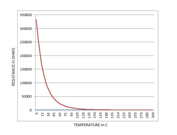
To grasp the non-linear nature of thermistors, look at the EPCOS Rnom column in the summary table. The 100k-ohm spec on our EPCOS thermistors refers to the thermistor resistance at 25 degrees C, and the table reflects that. Note how around room temperature a 5 degree temperature change causes a resistance change of 20,000 ohms or more. At 200 degrees, a 5 degree shift only changes the resistance by about 50 ohms. For our 100,000 ohm thermistors, the temperature range between 185 degrees (arbitrary PLA) and 230 degrees (arbitrary ABS) only leads to a resistance change in the neighborhood of 432 ohms. When using our printers, we put a lot of measurement emphasis on such a small change in resistance at those higher temperatures. Here's a resistance-vs-temperature graph of the EPCOS data -
The Type 6 data in the Marlin baseline is likely someone's attempt to build a table using real-world measurements either on a printer or with a thermistor in a temperature chamber. This likelihood is supported by the comment for Type 6 in configuration.h that says it was compiled with a Fluke thermocouple. Without knowing more about how that data was collected, I have no idea how it might apply to my printer and I personally find it pretty worthless. The data is also immediately suspect since the same ADC count value is shown for both 40 and 45 degrees.
For whatever reason, the Type 6 thermistor data provided by MakerFarm has been altered to basically reflect Type 1. My guess is they or their firmware source inadvertently started using Type 6, didn't like it, and not realizing there was really another type they should use instead they modified the Type 6 data. Now there's really no significant difference in specifying the use of the Type 1 thermistor, or in specifying Type 6 AS LONG AS you are also using the MakerFarm alterations to the Type 6 table. Those that update their firmware from the Marlin repository will need to either switch to using the Type 1 data or need to carry forward the MakerFarm manipulation of the thermistortables.h file. Seems to me that switching to Type 1 is the preferred path. Using the Marlin type 6 data as-is could lead to temperatures that read as much as 20-30 degrees different than they used to be with the old firmware. Whoever built the Marlin Type 6 table was evidently OK with reading the temperature differently.
Except for the Marlin baseline data for Type 6, the thermistor tables involved here appear to be defining theoretical, perfect data not affected by real world factors such as thermistor self heating, temperature soak, drafts, or anything else that could affect the accuracy of the actual measured temperature. It's likely best to keep it this way rather than trying to build custom tables that factor real world observations measured on your printer with an independent thermometer or thermocouple. For one thing, otherwise you'd likely have to have different tablesets for your hot end thermistor and the heated bed since they'd act differently.
The tolerance of the 4700 ohm resistor used in the voltage divider with the thermistor contributes an error in the temperature measurements. Ideally, that part would be a high precision, low temperature drift part in order to minimize the error it contributes. Errors due to leakage currents in the 10uF capacitors used to filter the voltage divider output should be insignificant. The absolute voltage of VCC is irrelevant, since the ADC is set up to use VCC as full scale. Since VCC is also used to source the voltage divider, any error from nominal 5V will affect both the voltage divider output and the ADC sampling, for no net effect.Last edited by printbus; 05-02-2015 at 09:02 PM. Reason: migrated to offsite attachment storage due to 3DPrintBoard issues


 Reply With Quote


Do bed magnets deteriorate.
04-29-2024, 01:35 AM in General 3D Printing Discussion