


Results 1 to 10 of 25
Thread: Garbled LCD screens
Hybrid View


-
08-21-2014, 04:12 PM #1Staff Engineer

- Join Date
- May 2014
- Location
- Highlands Ranch, Colorado USA
- Posts
- 1,437

Recovery from garbled Marlin LCD display
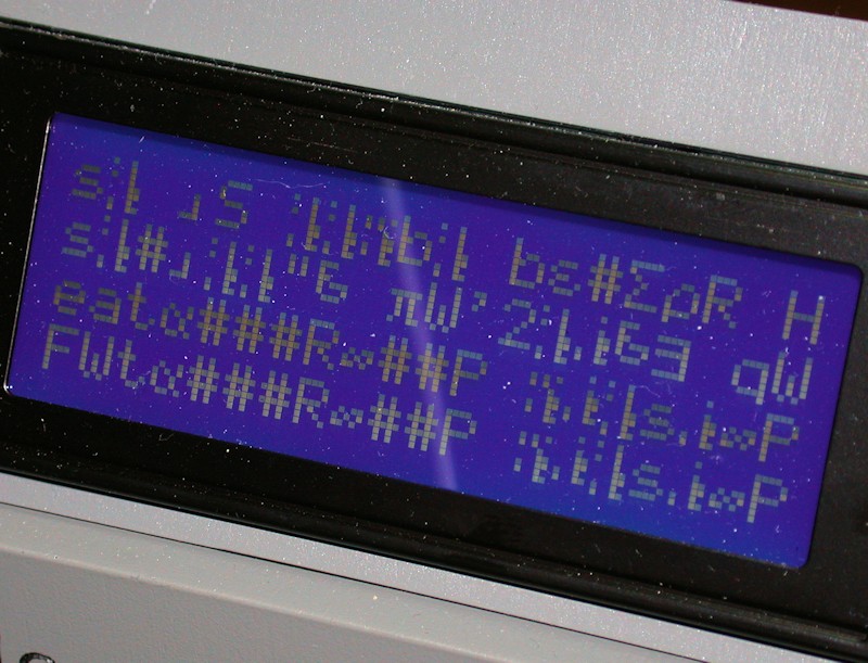
How prevalent is the problem of the Marlin LCD panel displaying garbled data? My MakerFarm 8-inch i3v does it once in a while - often enough to just be annoying.
Having written LCD interface code before, I've looked at what is supposed to be displayed and the actual garbled display. Turns out the screen effect is very predictable once it gets into this garbled mode. I have an idea for a firmware change that would recover from this, but I don't want to futz with it if this isn't a common problem.
EDIT: My reluctance to futz with this is simply that I'm new to looking at the Marlin software and it would take me some time to figure out how the LCD interface is implemented. If there's someone out there that already understands the interface, I could share what I think we could do to fix this so that person could give it a whirl.
Last edited by printbus; 05-02-2015 at 08:32 PM. Reason: migrated to offsite image storage due to 3DPrintBoard issues
-
08-21-2014, 04:43 PM #2Super Moderator
- Join Date
- Apr 2014
- Location
- Lone Star State
- Posts
- 2,182
Unfortunately for you.... I don't have an LCD Panel or I would jump in and help you! There are a lot of different modules and communication methods for the different panels. It might make sense to see which panels are 100% reliable and compare their interface code against what you have. If you can get consensus on what the most reliable one is... I'll take a look. It might be they have pushed the timing or something a little bit too far and warming over the interface code makes things better. But that is pure speculation.
-
08-21-2014, 05:23 PM #3Senior Engineer
- Join Date
- Jun 2014
- Location
- Burnley, UK
- Posts
- 1,662
That is a whole lot more than speculation, it is years of hands on experience. Originally Posted by Roxy


-
08-21-2014, 10:31 PM #4Super Moderator
- Join Date
- Apr 2014
- Location
- Lone Star State
- Posts
- 2,182
OK.... I believe its real.... But it might not be the interface code... I'm just making stuff up... If there is a stack overflow condition or a bad pointer being de-referenced in a loop, you can make all kinds of data corruption happen.... My guess is they are pushing some I^2C timing or something too hard. What happens a lot of time is people make firmware based timing loops and when the processors speed up, the timing doesn't work any more. I really don't know at this point. The good news is, I don't have an LCD Panel to look at... I can just sit here and speculate! What a sad world! Originally Posted by Mjolinor
-
08-21-2014, 05:58 PM #5Staff Engineer
- Join Date
- May 2014
- Location
- Highlands Ranch, Colorado USA
- Posts
- 1,437
What I've seen so far in the code is pretty generic, thanks to the Hitachi controller chip and clones that pretty much every LCD uses. The Marlin code quickly leverages Arduino library stuff for the LCD functions.
-
08-21-2014, 07:44 PM #6Staff Engineer
- Join Date
- May 2014
- Location
- Highlands Ranch, Colorado USA
- Posts
- 1,437
Oh, what the heck. I have a firmware change uploaded to test. I'll post details after I run this a while to make sure there are no ramifications of the change and after I witness the display recovering from "garbled mode".
The fix is oriented around LCD interfaces that leverage the 4-bit or nibble mode to send data to the displays. As best I can interpret the possibly dated code base from MakerFarm that I'm working with, this will be the case for those with a configuration.h file that has #define statements for ULTIPANEL, REPRAP_DISCOUNT_SMART_CONTROLLER, G3D_PANEL, or ULTIMAKERCONTROLLER. These in turn will invoke the ULTRA_LCD stuff that is important here.
In the 4-bit data mode, two transfers to the LCD display are required for most commands and data characters. The problem is that if we miss a transfer or double-clock one due to static, noise, firmware timing, or whatever, the data being sent to the display gets out of sync. For display characters, data gets displayed that is say the last four bits in one character and the four bits from the next character. This out-of-sync error will remain until the Arduino board is restarted or reset.
There's an easy way to prove this theory for those running the printer from a host like Repetier that allows you to send G-code commands in real time. If you see the display garbled, send this to the printer without the quotes: "M117 ccccccccc" (be sure it is lower case). When things are working properly, this should cause the string of c's to be written to the status line at the bottom of the screen. In garbled mode, a string of 6's will be printed somewhere instead. Why 6's? The character address code for "c" is binary 01100011, and is sent to the display in two transfers consisting of 0110 and 0011. When things get out of sync the LCD will read these repetitive transfers in as 0011 and 0110 instead, or 00110110 combined. That's the character address code for the number 6. The location of the 6's may be somewhere other than the bottom row; it's likely that command messages can get messed up just like the character address messages.
The display modules support 8-bits of character codes. The predefined character sets in the display modules supplement the normal 7-bit ASCII alpha-numeric character set with 128 Greek and other symbols. Once the character data transfers get messed up, it doesn't take much for characters to be selected from the extra symbols. If you have a font table for one of the Hitachi-based LCD modules and the display is garbled, you can use the M117 command to play around with how different "intentional" characters get misinterpreted as stuff in the extended character set, etc. You could even use the font table to reverse things and decode what a garbled display is trying to tell you.
What I've uploaded to test is a one-line code change that reinitializes the LCD interface whenever the display will revert back to the main status screen. When the garbled display occurs, simply letting the display timeout should restore things. If the main display itself is what's garbled, pressing the panel knob and then waiting for the timeout that returns to the main status display should restore things.Last edited by printbus; 08-24-2014 at 02:59 AM.
-
08-22-2014, 05:34 PM #7Staff Engineer
- Join Date
- May 2014
- Location
- Highlands Ranch, Colorado USA
- Posts
- 1,437
Looking good. Should someone want to add the display auto-recovery, here's the change. In file ultralcd.cpp, look for...
and add one line to it...Code:#ifdef ULTIPANEL static void lcd_return_to_status() { encoderPosition = 0; currentMenu = lcd_status_screen; }
The lcd_implementation_init function already exists. It calls the lcd.begin Arduino LiquidCrystal library function that takes care of initializing the display module. It also sets up a handful of custom character bitmaps like the thermometer symbol, and then it clears the display. I found that just calling lcd.begin would sometimes leave the custom character bitmaps incorrect, so I ended up adding the full init. The only time this additional code is executed is when the LCD display is about to return to the top status screen. The change won't be incorporated unless your configuration.h file invokes the #define for ULTIPANEL.Code:#ifdef ULTIPANEL static void lcd_return_to_status() { encoderPosition = 0; currentMenu = lcd_status_screen; lcd_implementation_init(); // added; reinitialize the display module to recover from garbled display mode if happening }
FOLLOWUP COMMENT: Looking into the LCD code some more, I see the same lcd_implementation_init is already included as part of software detecting SD card insertion and removal. That code even has a comment with it that talks about how it is an attempt to recover the display from a possible static discharge. So, for a printer standing around doing nothing, just inserting or removing the SD card will also reinitialize the display module, without having to make this change.
Last edited by printbus; 08-24-2014 at 03:24 AM. Reason: code tags!
-
08-22-2014, 12:04 AM #8Staff Engineer
- Join Date
- May 2014
- Location
- Highlands Ranch, Colorado USA
- Posts
- 1,437
To clarify for the interested, the interface involved with at least these display panels consists of six dedicated pins on the Arduino processor. i2c isn't involved. SPI is ran to the panel on at least the RepRapDiscount smart controller, but it is used with the SD card, not the LCD module. The six pins consist of an enable, a register select, and four parallel data lines. Low level operations involved with setting the data lines and toggling the enable and register select pins are accomplished through Arduino LiquidCrystal library functions. Marlin code takes care of higher level stuff like menu structure.
It could be there's more than one thing going on, but static discharge is definitely a way I've seen my display mess up.
-
08-22-2014, 09:02 AM #9Super Moderator
- Join Date
- Apr 2014
- Location
- Lone Star State
- Posts
- 2,182
I don't remember why I was thinking i^2c was used. I think I was looking at some of the smaller Arduino boards that had less I/O pins and that ended up being how a given LCD Panel worked with it. Your explanation about each character being transferred as 2 nibbles is helpful. I think what you are saying is there is no signalling to the LCD Panel to tell it which 1/2 of the character it is receiving. It just starts in the right state and every other nibble that is transferred to it is the start of another character. That seems like it is just asking to get out of phase if anything unexpected happens. Originally Posted by printbus
It would seem they should have some way to reset the panel and get it to a known state???
Another question is this: Since a lot of the LCD Panels use the same support chip, does this happen equally often with all of them? Or does it mostly happen with specific Arduino boards? Is there some combination that is more prone to the display getting out of sync? Is it at all related to how clean the power is? I know my PrintrBoard had trouble powering the Servo for Auto Bed Leveling. Do the LCD Display boards grab a lot of power from the Arduino board?
The reason for the questions is if the root cause of the LCD Panel getting out of sync is because of missing or double clocking of the nibbles... It would seem slowing that down and making sure there are nice clean edges to the Enable and Select lines after the data is stable would help. Right? But if the corruption happens because of noisy power or something else, the solution will be doing things to clean that up.
UPDATE: And the more I look at this, the more I don't know. Pulling up this link: http://www.reprap.org/wiki/RAMPS_LCD it shows how to build the LCD Panel and it claims it is enabled by taking the comments off of the #define ULTRA_LCD line. But when you look at their directions, they are saying the LCD Panel has 8 data lines and they only hook up 4 of them???? It would seem they should have some 'illegal' combination of RS, R/W and Enable that causes the display chip to reset????
Oh and here is at least one example of an LCD Panel using i^2c: Check out: http://blog.reprap.org/2008/10/new-b...oller-v10.html That must be why I was thinking they were using i^2c in general for this stuff.Last edited by Roxy; 08-22-2014 at 10:08 AM.
-
08-22-2014, 10:23 AM #10Staff Engineer
- Join Date
- May 2014
- Location
- Highlands Ranch, Colorado USA
- Posts
- 1,437
The display modules DO have 8 data lines, but the controller chip supports a data transfer mode that only uses four of them. The modules also have a read/write signal, but common applications don't need to read anything back from the display so they're hardwired for write-only. Using the 4-bit mode saves Arduino pins. (I'll get to i2c savings later) Originally Posted by Roxy
One would think, but no. "Initialization" involves sending a particular sequence of commands to the display module, with specific timing constraints on the transfers. That's all my "fix" is doing - periodically reinitializing the display by going through that command sequence again. There's a bit of delay in doing this, but I don't notice it on my printer. If I understand Marlin right, any printing going on should be handled in interrupts, so the additional time spent reinitializing the display shouldn't affect anything. Originally Posted by Roxy
I think there's too many variables here. I've had static issues on non-printer and non-Arduino designs using the modules, minimized by simply putting the display behind a bezel. They don't all use the same Hitachi HD44780 controller chip. There are clone chips out there. Older boards have discrete chips. Newer boards have the substrate right on the board and coated over. They just all support the same command set as the original HD44780 chips. Then, there's different module circuit board layouts that could lead to differences - maybe trace routing differs, different ground distribution, or maybe some include decoupling capacitors, who knows. Also, maybe some of the Arduino clone boards are better quality than others. Cleanliness of the power supply could make a difference. Wire routing in the printers could make a difference. Originally Posted by Roxy
The core of the LCD modules I've used only need a couple of milliamps of power. If used, a backlight will draw more, but displays with the typical LED backlighting will still be relatively low. I would assume that those reprap displays with the rotary encoder and SD card still draw minimal power.
---------------
Rather than ramble on here, I'll touch on i2c in another post.Last edited by printbus; 08-27-2014 at 01:33 PM.


 Reply With Quote


QIDI Slicer "Plater" is...
04-12-2024, 02:21 AM in QiDi 3D Printer Forum