


Results 41 to 50 of 255
-
06-08-2014, 09:00 AM #41Staff Engineer

- Join Date
- May 2014
- Location
- Highlands Ranch, Colorado USA
- Posts
- 1,437

BED LEVELING
The bed leveling concept for the i3v seemed pretty straightforward. Adjust the Z endstop for the desired hot end clearance over the fixed-height home corner of the bed, and then adjust the other three corners to match the clearance. Yeah, right. I found it impossible to adjust the Z endstop with any accuracy or repeatability, especially since even a slight change in the angle of the switch makes a big difference when you're adjusting to paper thickness clearance. When I lucked into a Z endstop position that might work, adjusting the other three corners was tedious, having to repeatedly move the bed and then switch between adjusting the height and checking clearance.
Rather than revamp the Z endstop design, here's what I implemented to provide an easier adjustment. The Z endstop will be left at a fixed height. All four corners of the heatbed are now adjustable; I found a spring somewhat like the other three to use on the home corner and removed the spacer. M3 x 30 bolts now used in each corner, with a locknut installed to fix the bolt to the heat bed so it won't rotate. Springs between the locknuts and the Y bed. The springs Makerfarm provided in the kit slip perfectly over the round end of the M3 locknuts. M3 wing nuts or thumbwheels under the Y bed for adjustment. Z endstop switch set generally where it should be for the spacer height that used to be in the home corner, and will no longer be adjusted.
Tired of spending money at the hardware store for this thing, I thought I'd try printing some M3 thumbwheels to use under the Y bed. I was surprised to no end when the first print I've ever done came out usable, especially with the Z axis stepper motor running with an indeterminate current limit setting because of the damaged driver board.
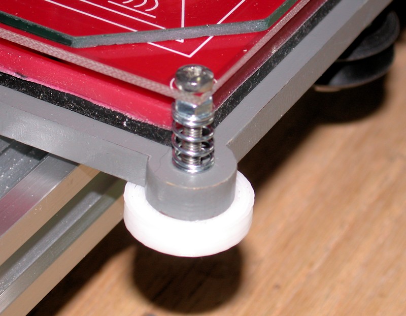
After adopting this approach, adjusting the bed for proper clearance in all four corners is trivial, and requires no tools. It took just a minute or two to tweak thumbwheels using a piece of paper for a gauge before subsequently printing my LCD knob. The surface area between the Y bed and the thumbwheels seems very adequate for keeping the thumbwheels in position.
I'm sure the concept of the thumbwheels isn't new, but I have no idea who to give credit to.
FOLLOWUP COMMENT: BTW, my bed leveling process starts with using the long straightedge to check for proper adjustment between the X motor plate and the X idler plate like I did during the X axis alignment. Z rods rotated as necessary to get them aligned with each other. I figure any mismatch from how I aligned them previously will lead to some torsion in the X axis, possibly increasing the chance of a Z motor skipping a step or doublestepping.
FOLLOWUP COMMENT #2: The design of the first M3 thumbwheels used includes a fine ridge for grip that didn't come out on my print. When I wanted to reprint the thumbwheels in black, I went for a different design with more a pronounced finger grip although I did have to file down the ridges a bit on the left rear position to clear the frame.
FOLLOWUP COMMENT #3: The Z endstop switch implementation was later revamped to a screw-adjustable design. That's a far better implementation.
FOLLOWUP COMMENT #4: The original post mentioned M3 x 30mm bolts being used in each corner. I think they are actually M3 x 25mm.
FOLLOWUP COMMENT #5: I later realized a significant advantage to the different design thumbwheels installed later. That design has 10 ridges around the circumference of the thumbwheel. With the 0.5mm pitch for the M3 hardware, this equates to 0.05mm in height adjustment for each ridge. In switching between printing directly on glass and then printing on painters tape, I can get very close to an initial adjustment by just rotating each thumbwheel by two notches to adjust the bed 0.1mm in height.
FOLLOWUP COMMENT #6: For those with 10 and 12-inch printers, note that the thumbwheel approach here is implemented on an 8-inch printer. For the larger printers to get the extruder to the front of the print bed, the rear of the Y-bed will need to extend beyond the rear frame brace that goes across the back of the printer. That rear frame brace may need to be modified to provide the additional clearance needed for the thumbwheels and/or the bolts used in the two rear corners.Last edited by printbus; 05-03-2015 at 07:20 AM. Reason: migrated to offsite image storage due to 3DPrintBoard issues
-
06-09-2014, 08:03 PM #42Staff Engineer
- Join Date
- May 2014
- Location
- Highlands Ranch, Colorado USA
- Posts
- 1,437
GARBAGE DATA ON LCD DISPLAY
The LCD screen has frequently been displaying garbled data. Initially this was when I was trying to do something with the rotary encoder. I thought static was perhaps being passed through the metal knob I had on the encoder, but I still saw the display get messed up at random during prints after replacing the knob with a plastic one.
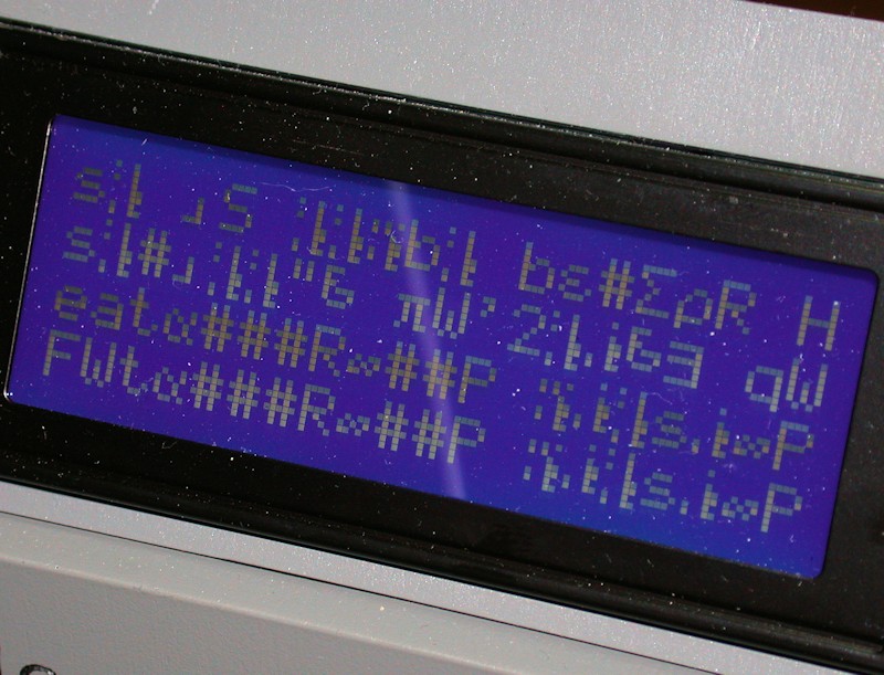
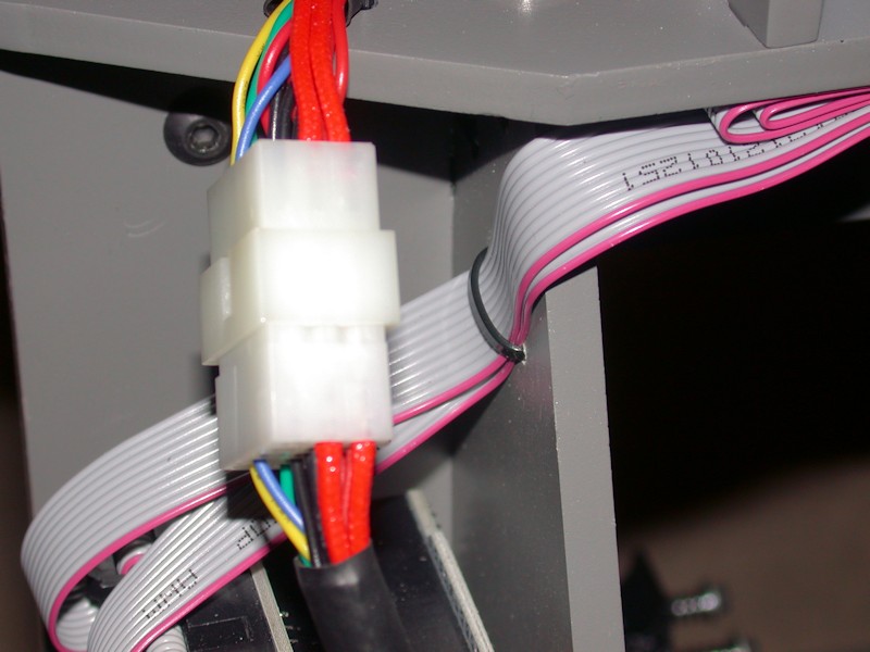
I've written microcontroller software for similar displays before. For those that don't know, with these displays characters can be displayed from an ASCII character set, an alternate character set, or a number of user defined character bitmaps. While the specifics of the alternate character set vary by manufacturer, some of the characters I see on my screen are typically found in the alternate character set. I'm not sure how data from the alternate character set is being written to the LCD, but others with the Marlin-type display have reported the problem often is noise coupling into the LCD ribbon cables. My ribbon cables were touching the X carriage cable harness passing over the top of the printer. I drilled a few holes in the right side of the frame and added a zip tie to pull the ribbon cables away from the X carriage harness. Looking good so far, although I've only ran one two hour print job since the mod. Next time I'm ordering from the likes of Mouser or Digikey, I'll likely order new connectors for the ribbon cables and shorten them up, which others have also reported as an occasional fix.
FOLLOWUP COMMENT #1: Moving the ribbon cables has definitely helped. There still is a sensitivity, however, to fingers reaching over the top of the frame and touching the LCD circuit board when reaching for the knob.
FOLLOWUP COMMENT #2: After a few months, I got around to building new, shorter ribbon cables. I'm not sure that made any difference. An explanation on what is happening that results in the garbled display is discussed in the Garbled LCD Screens thread in the Firmware Enhancements to Marlin area.
FOLLOWUP COMMENT #3: Looking into the firmware associated with the LCD panel, I grew to realize that the existing firmware base has a built-in provision for restoring the display once it gets into this garbled mode. Assuming the printer isn't busy printing from the SD card, insertion or removal of the SD card will restore the display to proper operation.
FOLLOWUP COMMENT #4: Newer versions of Marlin have yet another built-in recovery scheme. When the printer is at the top status screen, pressing in on the panel button will also restore the display.
FOLLOWUP COMMENT #5: I'm still getting the garbled display a lot. While it does usually happen when I touch the display, I have seen the display garbled during a print when I haven't been close to touching the printer.Last edited by printbus; 05-03-2015 at 07:22 AM. Reason: migrated to offsite image storage due to 3DPrintBoard issues
-
06-11-2014, 01:55 PM #43Staff Engineer
- Join Date
- May 2014
- Location
- Highlands Ranch, Colorado USA
- Posts
- 1,437
HEAT BED CLIPS
Binder clips in the SMALL size are the common method of clamping the print surface to the heat bed. I found the MINI size works out better. Even installed all the way, they aren't as likely to protrude into the printable area. The smaller wire wings also keeps them from getting in the way, so they're easier to just leave on.

For a clip installed to the rear left side of the heat bed, bending the wings a bit allows the clip to clear the left sidewall of the frame. Leaving the wings in place makes it easier to remove the glass, so I'm likely to clean it more often.

MICRO sized binder clips are also available, but I don't think they open wide enough to grab both the glass and heat bed when using 3mm glass.
FOLLOWUP COMMENT: Note that I am using glass that goes from one edge of the heat bed to the other edge, or about 8-3/8 inches in width. This allows me to use clips that don't encroach into the print area, minimizing the chance that the hot end nozzle will hit a clip during homing, etc.
FOLLOWUP COMMENT #2: IIRC, I obtained the mini clips from the office supplies area at Walmart. I think they came in a package of 70 for $4 USD.Last edited by printbus; 05-03-2015 at 07:25 AM. Reason: migrated to offsite image storage due to 3DPrintBoard issues
-
06-14-2014, 06:12 AM #44Staff Engineer
- Join Date
- May 2014
- Location
- Highlands Ranch, Colorado USA
- Posts
- 1,437
WRAPUP COMMENTS ON THE INITIAL BUILD
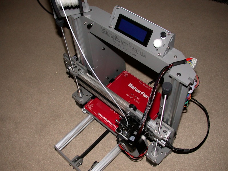
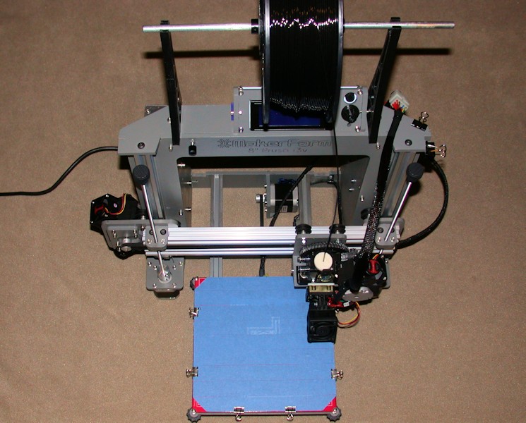
After completing about a dozen items and calibration prints, I'm pretty content with my decision to build the i3v. It appears to be very capable, yet obtained at the lower end of the price range for 3D printers without having to gamble on a crowdfunding effort. Yeah, I spent a lot of time building it, but I knew I would going in. Others have shown you can get an i3v functional without as much extra effort. For the long haul, I know I've got good support available at MakerFarm, and the parts are mostly generic and available elsewhere.
I found it extremely helpful for MakerFarm to have provided configuration files for Slic3r and for the electronics to arrive preconfigured with firmware for the i3v. This allowed me to get the printer up and running without having to fret over configuration and firmware download details that I wouldn't have understood at the time. I can now work through them as I learn more about printing and the i3v printer.
KEY BUILD POINTS
Expect to use the MarkerFarm build guide and build videos only as a guide. Don't assume they tell you everything. Think about what you're doing, and be ready to fill in the missing details yourself. Post questions on the board here or contact Colin. I only asked him two questions, and got responses quickly.
Watch for hardware fit conflicts. Some things won't fit if adjacent nuts aren't rotated right. I had some X carriage screw heads rubbing on the X axis extrusions, and had issues with the length of the bolts on several of the X carriage and X idler wheels. Several holes required elongating. This may be more personal opinion than fact, but work to eliminate any mechanical slop in the hot end tip when you have the extruder done. It seems to me that you can't expect good prints if the hot end tip isn't fairly rigid.
DESIGN CONCERNS
Here are my concerns with the i3v design, regardless of whether they're systemic to the Prusa i3 or specific to the MakerFarm i3v. While I call them concerns, remember I'm still happy with the i3v. Resolving these issues would make the thing pretty perfect as far as I'm concerned.
- Adjusting bed clearance with the Z endstop switch and a fixed spacer between the heatbed and Y bed at the home corner. What a pain. Leaving the endstop position alone and adjusting the heatbed height at all four corners is perhaps the best mod I did to the i3v.
FOLLOWUP COMMENT: Clough42 has been posting great things for the i3v on Thingiverse, including parts for a screw-based Z-stop adjustment.
- Lost capacity in the X axis. The X motor mounting plate limits how far the X carriage can move to the left. I had to get creative to find ways to allow the extruder to move farther to the right in order to achieve the specified 200mm range in the X axis. Why couldn't the X axis aluminum rails be a bit longer and the frame stretched a few mm to resolve this?
- Rinky dink approach to the Y idler that requires tinkering if you don't want the belt rubbing on the wood brackets. Issues here are exaggerated by misalignment between the Y bed belt mount and the Y idler. Why don't they line up better? The X idler design is similar, but at least there it's easier to adjust the angle of the bolt holding the pulley bearings as a belt adjustment.
FOLLOWUP COMMENT: A custom belt guide wheel has recently been added to Thingiverse, with an improved one at http://www.thingiverse.com/thing:790138. This would resolve the Y idler concern, and could also be used on the X idler.
- There are worrisome places I can see the wood plates flex. Pressing back on the Y idler front just a bit causes the Y belt to sag. If I manipulate the Z motor cases by hand, I can see the frame sidewalls flex. Maybe neither is significant, but reinforcements could have been readily added to prevent both. I'll also be watching for warping in the Y bed since it's always under stress from the heat bed springs.
Last edited by printbus; 05-31-2015 at 08:34 AM. Reason: migrated to offsite image storage due to 3DPrintBoard issues
-
07-19-2014, 10:54 AM #45Engineer
- Join Date
- Jul 2014
- Location
- Eastern Colorado
- Posts
- 536
Huh, so that's what those holes are for. My heat bed relay melted when I was still using the i3, and I haven't fixed it yet. I've been using the relay mount holes as a place to zip-tie up the cables for the heat bed. Originally Posted by printbus

-
07-20-2014, 03:41 AM #46Staff Engineer
- Join Date
- May 2014
- Location
- Highlands Ranch, Colorado USA
- Posts
- 1,437
Yep. I can't speak to the i3, but the i3v build guide mentioned that's what the small hole pattern was for. The frame could stand a few holes for adding zip ties at both the RAMPS and heater relay; I thought about drilling some but ended up using 1/4-inch cable clamps instead. Originally Posted by AbuMaia
-
07-31-2014, 01:19 PM #47Staff Engineer
- Join Date
- May 2014
- Location
- Highlands Ranch, Colorado USA
- Posts
- 1,437
SIX WEEK STATUS UPDATE
After about five dozen prints, I'm still content with my decision to go with the i3v. Primarily thanks to Thingiverse, I've pretty much got the hardware where I want it to be for now...
SLICER
After futzing and researching, I've opted to focus on Cura as my slicer. Working with both v0.9.9 and v1.1.6 in Slic3r, I just grew increasingly frustrated with gcode conversion taking so long or not completing, with some prints having gaps left behind while on other prints excessive time seemed to be spent on gap/hole touchup, with nozzle moves that do not follow logic, with some prints coming out better in v0.9.9 while others did better in v1.1.6, and with support capability still being somewhat lacking. Some of these issues may be user error in dealing with the 100+ settings in Slic3r, and at some point I may want that detail of control back, but for now I'm doing great with the subset of controls Cura provides.
FOLLOWUP COMMENT: When Repetier baselined Cura as an integrated slicer, I migrated to that. I'm liking it. It provides a nice interface that integrates printer manual control, slicing, layer by layer review of the slicing result, printing, and layer-by-layer monitoring of what the printer is doing.
PRINT SURFACE
With the hairspray-on-glass surface I had been using, I battled getting the first layer of PLA to stick with Cura. At all. Research indicated others have also had first-layer problems when switching to Cura. Changing pertinent settings and moving to printing on blue painter's tape with no heat applied helped, but not enough. For me, the magic combination seemed to be the settings and blue tape, along with wiping the painter's tape down with isopropyl alcohol after installing it and then adjusting the nozzle clearance with the nozzle hot. I wasn't expecting to have to re-engineer the first layer approach just because I went to a different slicer. There's definitely a difference in how the first layer is handled.
LEVERAGING THINGIVERSE AND OTHER MODS
So far, I'm not into designing my own stuff to print. I'm busy enough with just figuring out the printing side of things. Here are the things I've incorporated into the i3v...
I swapped out the original thumbwheels under the heat bed with ones that have more knurl - http://www.thingiverse.com/thing:29782. The one at the rear left corner was filed down just a bit to clear the frame side wall. To recap, on my printer all four corners of the heat bed are adjustable. Screws are locked to the heat bed, and the thumbwheels go under the Y-bed. It takes about a minute for me to check and adjust level around the bed. I'm currently seeing no issues driving me to incorporate automatic bed leveling.
FOLLOWUP COMMENT: A side benefit to these thumbwheels is that they have 10 ridges around the circumference. At 0.5mm pitch on the M3 screw they are mounted on, each notch in rotation equates to a 0.05mm height adjustment in that corner.
I swapped out the LCD knob with one that just looked better - http://www.thingiverse.com/thing:385882
For a spool mount, I migrated to brackets that hold the spool directly above the top plate on the i3/i3v - http://www.thingiverse.com/thing:192510. There are multiple bracket designs that hang the spool to the rear, but I didn't like the idea of that weight putting torque on the top plate. The spool I have from MakerFarm with 1.5-inch spindle got a pair of these hubs with bearings - http://www.thingiverse.com/thing:7853. My other spools with dual-size spindles use prints derived from http://www.thingiverse.com/thing:28046.
FOLLOWUP COMMENT: I found there's a side benefit to the spool being on a wide rod. I ended up with shaft collars on each side of the spool, and the shaft collars are tightened to the rod. I can adjust the spacing of the shaft collars to put just a bit of drag on the spool. This has been really helpful in keeping the windings on the spool layered properly. I found that if the spool spins too freely, the spool can start to unwind itself and loosen up several turns of filament. This could eventually lead to feed issues.
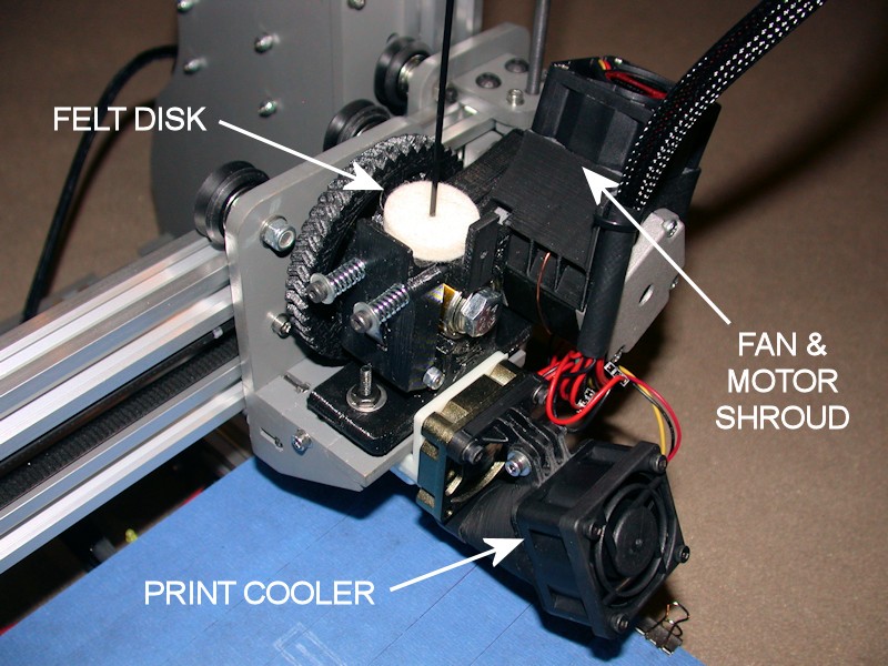
It's not Thingiversed, but I now print the cooling shroud for the hex hot end in ABS so I can easily cut out the bottom of it to clear the nozzle body of the hot end. Whose idea was it to have the printed cooling shroud snap onto the hot end and rest on the aluminum block where, um, PLA and ABS gets melted? I added some kapton tape to the top surface of the hot end block to help insulate the block from the hex cooling fan airflow. I also swapped out the noisy hot end fan MakerFarm with a quieter one. The first one was around 5 CFM but super quiet. This was OK with PLA, but the extruder base started getting soft when I started working with the higher temperatures of ABS. The current fan is only spec'd at about 6 CFM, but has a higher speed that can probably do better at pulling air through the shroud.
FOLLOWUP COMMENT: I later added wings to the rear of the shroud to ensure airflow is forced onto the hot end heatsink. See EXTRUDER REBUILD AND NEW PRINT COOLER (Part 1).
In the original build, I futzed with the X and Y idler alignment so that belts wouldn't drift to the side and rub against the wood of the mounting brackets. I no longer had a problem to solve, but as a design improvement I printed and installed a pair of these belt guides - http://www.thingiverse.com/thing:359773. I installed them with three washers - one on each side and one used as a spacer between the two bearings that press into the belt guides. The belt lengths needed to be increased a few teeth, but I had left enough excess length before to cover this.
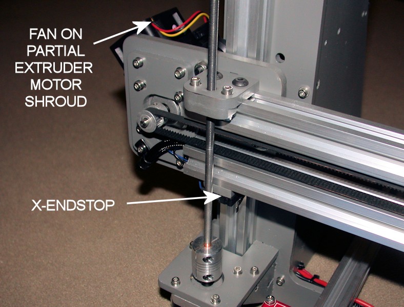
Clough42 has a pretty slick cooling shroud for adding a 40mm cooling fan to the extruder motor - http://www.thingiverse.com/thing:343026. I'm using a fan that doesn't put through the air that the one in his Thingiverse picture does, but I used what I could find locally and wanted to lean towards the quiet side as a starting point. Rather than cover some of the motor metal with a zip tie to strap on the shroud, I used a loop of solid wire as an attachment in addition to the snug fit the shroud already has on the motor. While the design is great, as a non-expert I found it to be one of my more challenging prints to date. Six or eight attempts ended up in the trash. One, the grid that faces the motor appears to not show up until the second layer (although I did get some gcode from Slic3r 0.9.9 that included it in the first layer), and many prints would start out bad because of this. Two, one side of the shroud has a pretty good slope to it that I found challenging. Three, I'd typically end up grinding into the filament when the end was near and I'd only be adding small layers to the "uprights" in the print structure. I'm sure the latter issues were my own doing - especially my retraction settings. I printed another after getting Cura somewhat figured out and a print cooler installed - that print turned out far better, first shot.
FOLLOWUP COMMENT: I have the motor type that runs hot. A cooling fan for the extruder stepper motor may not be required by all MakerFarm kits.
FOLLOWUP COMMENT #2: In EXTRUDER REBUILD AND NEW PRINT COOLER (Part 1), I ultimately replace the hot-running motor with a different one.
Filament now passes through a Dremel "felt polishing wheel" added to the top of the extruder to wipe the filament clean. This was added after I found the need to unroll quite a length of filament to remove some twists showing up towards the end of a spool of white filament. Enough of the filament was unrolled that it ended up on the floor. My print area has black and dark grey commercial carpet, and we have two black cats and a small dog with short black hair that hang out in the same area. Need I say more?
I've incorporated Clough42's print cooler - http://www.thingiverse.com/thing:351280. It fits best without the stock hex hot end cooling shroud and fan in place, but my glued-together X-carriage and undermounted LED lighting doesn't lend to incorporating his alternate hex hot end cooling system, and I'm not sure the alternate system will handle cooling for ABS. I just mounted it in addition to the hot end shroud and fan, and I've been playing with extending the print cooling shroud with large heatshrink. My PLA prints are definitely coming out better with this. I tried a couple different fans, and ended up sticking with an Adda fan with 10 CFM at 7800 RPM. The lower RPM isn't too obnoxious at full speed, even though the speed can usually be dialed back either via the slicer setup, LCD, or Pronterface/Repetier Host type software.
FOLLOWUP COMMENT: I've since removed the print cooler. Mounted on top of the hex hot end fan, it was likely blocking some of the hot end fan airflow. Combined with the low-flow fan I had on the hot end, this allowed the extruder base to soften up when I started printing at higher temps for ABS. So, I removed the print cooler and also put a stronger fan on the hex hot end.
FOLLOWUP COMMENT #2: The new print cooler approach is discussed in EXTRUDER REBUILD AND NEW PRINT COOLER (Part 2).
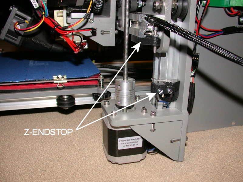
With a hefty pat on the back, Clough42 also has a replacement design for the irksome 8-inch i3v Z-endstop - http://www.thingiverse.com/thing:336665. This includes a new v-rail bracket for mounting the endstop switch on the right-side vertical rail, and a screw-adjustment bracket that mounts to the lower X-axis rail. Very cool and very functional. He also has printable brackets for the X/Y switches, but I've left mine wood for now.
One of the attempts at the extruder motor cooling shroud completed just enough that I could use it on the X-motor. It was either use it there or throw it away. The full length print would interfere with the delrin wheel(s) on the X-motor plate. I think this one stopped extruding at about the 85% point.
FOLLOWUP COMMENT: I have the motor type that runs hot. The temperature of the X-motor may not be an issue on all MakerFarm kits.
Finally, I swapped things around so that "home" is now in the forward-left corner of the print bed. This makes it easier to clean off the nozzle just before a print starts, and the print bed orientation is now the same as it is in the slicer and in Pronterface. There's firmware magic that could have done this, but for now I just moved the locations of the X and Y endstops and reversed the X/Y motor plugs on the RAMPS board. The revised Y-endstop uses the same post sticking down from the heat bed - the switch was relocated to just in front of the Y-motor. The X-endstop got moved to the left side of the printer. IIRC, both switches had to be moved to the other side of the mounting brackets. I've set up CURA to include endcode that brings the bed forward and moves the X carriage to the far right at the end of a print.
SPARE PRINTED PARTS
Only now do I think I've learned enough about printing and managing print quality to consider printing spare parts for the extruder. I've been on borrowed time with the extruder base that had started to split (note the large washer and nut that isn't supposed to on the extruder mounting bolt in the extruder picture).
FIRMWARE
I'm still running the firmware as supplied my MakerFarm. I haven't even enabled making EEPROM changes from the LCD, so I have to manually set the extruder feed rate all the time. This has actually been intentional for my situation. I've done a number of AVR-based microcontroller projects before, and I've seen a lot of forum-code and open-source stuff that really didn't have a lot of quality to it, especially in the Arduino world. I'm not saying that's true of the Marlin/RAMPS stuff - I certainly hope it's not the case. But by not even downloading the source code, I haven't been tempted to start "tweaking" it under the assumption that I thought I could do better.Last edited by printbus; 05-03-2015 at 07:34 AM. Reason: migrated to offsite image storage due to 3DPrintBoard issues
-
08-10-2014, 08:13 PM #48Engineer-in-Training
- Join Date
- Jul 2014
- Posts
- 204
Does your bed heat indicator LCD work? I noticed the wiring seemed different than that shown on the reprap wiki photos. Great looking build.
-
08-10-2014, 08:28 PM #49Staff Engineer
- Join Date
- May 2014
- Location
- Highlands Ranch, Colorado USA
- Posts
- 1,437
Thanks for the build comment! Originally Posted by TopJimmyCooks
I assume we're talking about the LED on the heat bed? Yes, it works. I didn't think to look at the reprap wiki on how to wire it up. I assumed the two parallel pad sets were for resistors - Without crunching the math, I figured maybe there was a power dissipation issue with using just one small surface mount resistor to provide the current limiting, and the intent was to put two resistors in parallel. I now see the wiki says to put two LEDs there in opposing polarities so that you know one of the two will light up. I just powered up the bed and when the LED didn't come on the first time, I unsoldered it and flipped it around. As long as the LED and resistor are both in series, it doesn't matter which one is "first".
When I reversed the LED, I also changed it so that the legs of the LED bend up at the edge of the heat bed. That way the LED sticks up above the heat bed and is visible from the front of the printer. All that said, there isn't much point to the LED. I hear the heat bed relay clicking on and off, and it's obvious soon enough whether the bed is warming up. As mentioned in the build post, I just added the LED since the heat bed had provisions for it.
EDIT: Before someone points this out, yes, the LED body is shaped so you can tell the + (anode) and - (cathode) leads apart. For some reason (too late at night perhaps?), I ended up soldering the LED on backwards even though I knew which way things had to go. Having probably wired up hundreds of LEDs before, it was embarrassing to see the LED not work right off the bat. Also, if the LED doesn't come on since it is reversed, one could also just swap the wires for the heat bed at the heat bed relay or RAMPS board. Polarity doesn't matter to the heat bed.Last edited by printbus; 08-11-2014 at 12:21 AM.
-
08-10-2014, 08:35 PM #50Engineer-in-Training
- Join Date
- Jul 2014
- Posts
- 204
I put the positive LED lead to printer "left." We'll see how it goes. may need to flip it around.


 Reply With Quote


QIDI Slicer "Plater" is...
04-12-2024, 02:21 AM in QiDi 3D Printer Forum