


Results 11 to 20 of 21
Thread: Skipped layers
-
08-25-2016, 03:42 PM #11Student

- Join Date
- Jul 2016
- Posts
- 18
The extruder is calibrated, but i am slightly overextruding at the moment due to an increased filament diameter. The filament increased in diameter to about 1.95 mm. However i am not certain about this because i do not trust my caliper, and that much overextrusion would be much more impactful. This causes excess plastic at 100% infill (solid bottom) causing the elephant foot. Originally Posted by Sebastian Finke

More so, overextrusion would not cause a LACK of filament on certain layers/skipped layers. In that case i think the retraction settings are more likely.
minimum distance: 1.5mm
retraction speed: 60mm/s
retraction amount: 2.5mm for some earlier prints and 1.5mm for later prints
travel speed: 150 mm/s
Combing: all
Although if this was the culprit i would expect to see this on all retractions, not just specific layers.
EDIT:
I am printing now with 1.5mm retration, blobbing and stringing increased. But no holes in this print so can not say anything about skipped layers.
EDIT:
Marked the filament 130 mm from the top of the extruder. Extruded 100mm at 100mm/min. The mark was 30 mm from the extruder top. 100mm/100mm was extruded, which should be ok. Ofcourse wiping the mark off with ethanol afterwards.Last edited by Reaping miner; 08-26-2016 at 05:25 AM. Reason: edited diameter (Borrowed a caliper) and added comment, added extruder calibration
-
08-28-2016, 01:22 PM #12Student
- Join Date
- Jul 2016
- Posts
- 18
Update:
I have printed some more of my diagnostic cubes with nut trap. And this problem is very repeatable. I have also taken apart my extruder and X axis, cleaning parts and reassembly. Checked various screws for tightness etc. No change. "skipped layer" problem is still there. I also want to add that i adjusted the flow ratio (92%) to account for the increased diameter from 1.75mm to 1.9mm.
However, i marked and watched the Z-axis motor couplers during the problematic layers. And they indeed turn half of a quarter turn (makes 1/8th) with a pitch of 0.8 mm makes 0.1 mm as the printer is supposed to move. This does mean that the problem i am seeing is not so much as underextrusion as caused by a skipped layer (increased layer volume due to higher height with the same amount of extrusion), but underextrusion for a different reason.
My new hypothesis:
The hydrophilicity of the (PLA) filament caused the filament to increase in diameter. This water vapor gets released in the melt zone and subsequently gets trapped there. (occasionally venting, somehow?) No retraction up to the first seperate layer of the M3 hole in the item. Upon retraction, the trapped (due to increased pressure after some time) vapor flows under the retracted filament. This vapor is trapped under the filament being pushed back in the melt zone and gets extruded before the filament, creating a gap in extrusion -> underextrusion.
This would also explain the large amount of filament that keeps flowing after extrusion stops. The vapor pressure keeps pushing the filament out of the nozzle until it reaches equilibrium with the surrounding pressue. This might also be the reason of the occasional temperature spikes i see at the start of a print (never had that before). It has been quite hot and humid in the printer room the past 6 weeks, usually 28-32 C at >80% RH. And i must admit i have been sloppy with my PLA storage after printing.....
I will try printing with my ABS soon. (It has been opened for a while but i stored it in a closed bucket with a bowl of oven dried silica beads.)
-
08-28-2016, 04:46 PM #13Student
- Join Date
- Jul 2016
- Posts
- 18
ABS only gave more problems. In addition to the "skipped layer" problem, after a few layers the nozzle started scraping the the print. At some point the infill and wall of the print came loose and i ended up aborting the print. (The infill also looked awful btw....).
Tried some more tivial settings.
-Lower retraction to 0.5 mm @ 40 mm/s (didnt give problems before)
-temp to 235 (ABS)
-checked calibration once again
-lowered speed to 20 mm/s
-travel speed to 100 mm/s
next things:
- check Z stepper voltage (Did slightly reduce some stepper voltages, not sure if i included Z or only lowered X and Y)
- check jerk settings
- General firmware settings check
As always suggestions are welcome.
-
08-28-2016, 05:46 PM #14Super Moderator
- Join Date
- May 2015
- Posts
- 989
Nozzle scraping the print is classic over-extrusion. That needs to be dialled in 100%. The quality of your walls is indicative of incorrect calibration. If your calipers are untrustworthy buy new calipers. Otherwise you're just wasting your time.
Filament has a diameter of 1.9mm? Poor quality filament imo. I have seen this before and it is impossible to calibrate as it is 1.9mmin one place then 1.6 in another. With a decent set of calipers measure a 2 metre length at 10cm interviews and see how much it varies.
Retraction: set retract distance to about 4mm and the speed to say 30mm. To short a distance will cause blobs/artifacts and stringing.
-
08-29-2016, 12:52 PM #15Staff Engineer
- Join Date
- May 2014
- Location
- Highlands Ranch, Colorado USA
- Posts
- 1,437

Moisture in the filament leads to steam bubbles that pop from the nozzle, often resulting in small bumps or zits in the print.
Re-reading the thread, I don't follow the height error you describe in post 1. The gcode snippet starts at a height of 3.65mm. A z-hop up of 0.75mm for moving to the next layer gets you to 4.40mm. The move to the starting location for the new printing layer includes moving Z back to 3.75mm, which would be the original 3.65mm height + 0.75mm z-hop hop - 0.75mm z-hop down + 0.1mm for the new layer height. How is 3.75mm the incorrect z-height for the new layer?
A new thought - PLA can tend to curl up at corners and edges - especially if the temp is a bit high or you're over-extruding. At your through-holes, perhaps this leaves a slight ridge that catches the nozzle on subsequent passes. This catching could cause a mechanical twitch throughout your x-carriage and extruder that leaves the nozzle a bit out of place until additional movement lets things settle back into place. Your 0.1mm layer height would be more susceptible to this than say a layer height of 0.2mm. Adding an effective print cooling scheme is very helpful in improving PLA print quality, and might be part of the solution you are looking for.Last edited by printbus; 08-29-2016 at 01:19 PM. Reason: removed some confusion
-
08-29-2016, 01:44 PM #16Student
- Join Date
- Jul 2016
- Posts
- 18
That is the reason i am not doubting my slicer program. The G-code looks correct, but the nozzle seems to be physically higher than it should be. Later i looked at position of the Z-axis couplers to more easily see if the Z-height physically does change like it is supposed to, it looks like it does. (1/2 of 1/4th turn is 1/8th turn translates to a Z difference of 0.1 mm which is correct.). Originally Posted by printbus
I actually was printing the extruder body to be able to add upgrades (read: layer cooling fan.).
So i bought new calipers today (Digital, 0.01mm). My old calipers seem to be a piece of junk.... The diameter of the PLA (BQ, pure white) and ABS (FFFworld ABS++ black) are very similar. The measurements of both rolls were:
1.76mm on average over the roll, with mostly 1.75 plusminus 0.01 mm in 9/10 measurements, one outlying measurement at 1.8mm.
Surprisingly though, i did get overextrusion symptoms. I am going to check the Z stepper voltage first.
Update:
Upped from 2.2A to 2.5A, still "skipping layer".
Update 2:
Switched to 0.4mm nozzle, same settings: issue persists but seems to be dampened or masked a whole lot better. At least this is more useable to print parts for things such as cooling solutions.
Update 3:
Switched to 0,2mm layer height, same settings: seems a little better than update 2. Infill seems to have improved a lot.Last edited by Reaping miner; 08-29-2016 at 05:03 PM.
-
09-02-2016, 07:23 AM #17Student
- Join Date
- Jul 2016
- Posts
- 18
Okay, i think i solved the problem. I woke up in the middle of the night for the usual reason people generally wake up. And i had an "eureka moment".
Hypothesis:
I hypothesized that i tightened the X-axis belt too much. causing the X-axis ends to be closer pressed to one another as there is no stop or end in the ends that prevents the smooth rods to slide too far in. This caused extra friction on the Z-axis linear bearings. In turn, this causes the Z-axis motors to convert rotational energy to compression energy in the flexible helical Z-axis motor couplers (basically a loading a spring). This causes a lag in movement after the Z-axis direction changes as the couplers release their energy stores first, until the drag force of the coupler overcomes the resistance of the Z-axis bearings.
Effect:
After homing: Overextrusion at print start
For homing the Zaxis moves down, then up a bit. and then again down, extending the coupler. This causes the coupler to compress for the first few layers, instead of increasing the Z-height until the coupler reaches an amount of compression that compensates for the Z-axis bearing binding.
Normal printing until the Z-axis direction changes: (i.e. the first Z-hop. (Before that exclusively upwards Zaxis movement.))
The Z-axis moves up the normal amount for the Z-hop, the motor couplers are already compressed.
However, when the Z-axis is supposed to move down, the motor coupler first releases its compression energy before dragging the Z-axis down after it is stretched sufficiently. Resulting in less downward movement than expected and printing too high.
This problem slowly resolves itself as the motor coupler gets more compressed during subsequent, non-z-hop layers (The Zaxis does not move, or moves less than it is supposed to, during this period) and layer height gets back to the set value. (Subsequent consecutive Z-hops would simply mostly compress and decompress the couplers and not actually move the Z-axis much during the Z-hops. However, the resulting net upward movement of the Z-axis will slowly compress the couplers on normal layers, much like at the start of a print.)
And then this cycle repeats on the next "first" Z-hop.
I printed my diagnostic cube with nuttrap with only minimal artefacts at the first Z-hop layer of the holes/nuttraps.
The solution(s):
Less tension on the X-axis belt (duh.) -> helps dramatically
Z-axis pretensioner -> http://www.thingiverse.com/thing:1044542 (Ironically i had these parts laying around for about a month now, but no bearings to install it. So i ordered these, among other things, yesterday and they should arrive today. So will also install these and let you guys know.
EDIT: Yes the pretensioner also helps, it does introduce something that looks like a small bit like Z-wobble, but small enough to live with. I will post a picture of the newly printed extruder body later. (If i do not forget.)
Strangely enough i havent been able to find anyone else documenting this problem.Last edited by Reaping miner; 09-03-2016 at 12:19 PM.
-
09-07-2016, 09:02 PM #18Staff Engineer
- Join Date
- Jul 2016
- Location
- South Florida, USA
- Posts
- 1,248

On the prusa i3's I have observed this problem happening from the threaded rods for the z axis passing through the small holes at the top of the frame. The threaded rods are just that. They are a far cry from the precision cnc smooth rods that the bearings ride on. If you hold the bottom and the top of the threaded rods in a fixed location, then the layers of your print can only show the out of round shape of your threaded rods. Cut the threaded rods just short of the top of the frame so the only thing the rods can touch are the stepper motor and the nut they spin through. As you make your next print, you can watch the top of the rod and see how far out of round it really is. And then you will see your good print quality
-
09-30-2016, 09:01 AM #19Student
- Join Date
- Jul 2016
- Posts
- 18
I simply bought a set of leadscrews, couplers and nuts. No Z-wobble anymore. I do have skipped layers on Z-hops again but thats because the Z-wobble from before screwed up the X-axis ends i needed to print (Very tight tolerances on those designs), causing my binding-sensitive RJ4JP bearings to bind on the Z-axis again.... (Actually visible compression and extension on the couplers when changing Z directions now). Trying to print a compatible X-axis endstop holder again first. (Without Z-hops ofcourse.) Then i will probably look into new, more suitable bearings for the Z axis or redesign the X-ends. RJ4JPs are just a huge pain in the ass to set-up. They are either too tightly conencted and bind, or they are too loosely connected and have play on either the inside or outside of the bearing..... Originally Posted by AutoWiz
Last edited by Reaping miner; 09-30-2016 at 09:13 AM.
-
09-30-2016, 11:32 AM #20Staff Engineer
- Join Date
- Jul 2016
- Location
- South Florida, USA
- Posts
- 1,248
Allow me to show you in pictures. The threaded rods for the z axis are too long. they are not supposed to pass through the top of the frame like this..
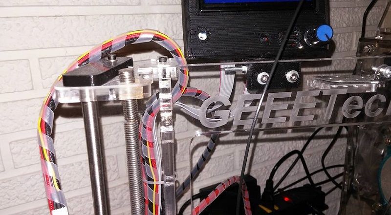
You can try opening up the hole in the top of the frame like this..
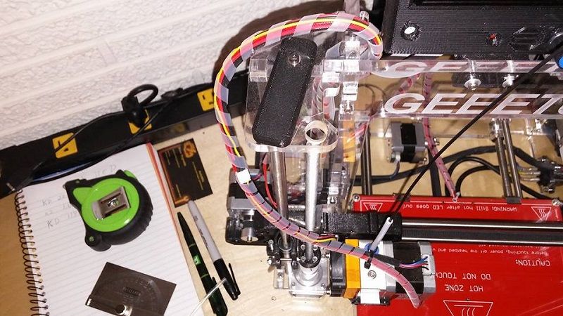
But really the right answer is to just cut the threaded rod to its correct and proper length like this..
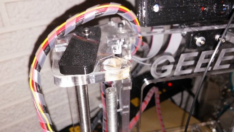
That hole is not a guide for the threaded rod. It is there so the rod can be installed and removed without the frame coming apart. Cut the threaded rod below this hole and watch the rod move around and not your print.

 Reply With Quote


QIDI Slicer "Plater" is...
04-12-2024, 02:21 AM in QiDi 3D Printer Forum