


Results 1 to 5 of 5
-
03-12-2015, 08:59 AM #1Administrator

- Join Date
- Jan 2014
- Posts
- 7,697

Stratasys Awarded 3D printing Seam Concealment Patent
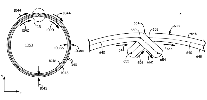
While desktop 3D printing is coming a long way, FDM/FFF processes typically leave something to be desired in the quality of finished prints -- most notably regarding the visibility of layers and the seams where layers meet. Stratasys has this week been awarded US patent number 8,974,715 B2 for a new method to control seams in FDM printing processes. The process, the brainchild of Paul E. Hopkins and Donald J. Holzwarth, is fairly technical and illustrated in the patent paperwork with complex diagrams, but the base idea is fairly straightforward. Their technique uses the printing of two exterior layers of a model that overlap on the object's interior, where the resultant seam is not visible. For a more in-depth look at the patented process, check out the full article: http://3dprint.com/50476/stratasys-patent-seams-fdm/
Below is an illustration from the patent filing:
-
03-12-2015, 11:10 AM #2Technician
- Join Date
- Oct 2014
- Posts
- 94
Yet another patent that doesn't pass the "obviousness" test. I'm sure they'll just use it to sue.
-
03-12-2015, 01:34 PM #3Student
- Join Date
- Mar 2014
- Location
- Swindon, UK
- Posts
- 36
Somebody skilled in the art will know this practice, which should fail the patent process due to prior art. As an experienced CNC programmer, the technique of arcing on and off a profile is well known in the machining and laser cutting fields to eliminate dwells and artefacts on the item. 3D printing is no different.
For Laser cutting example :
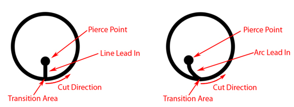
For CNC machining example, leading in at B(1,4) :

-
03-14-2015, 12:16 AM #4Engineer
- Join Date
- Aug 2014
- Location
- Montreal, Quebec
- Posts
- 576
Gyro, do you set in the software, or the piercing point and arc leads are done through the cad manually? Also, if I do in cad do I have to play with the vector order? Originally Posted by Gyrobot

I am having trouble with my laser cutted disk, they have this transition area that are just annoying.
-
03-19-2015, 02:25 PM #5Engineer-in-Training
- Join Date
- Apr 2014
- Posts
- 228
I'm pretty sure an older patent for the crossover trick for outer perimeters was why they sued Afinia. This seems to improve on that. The crossover would seem obvious to me, having worked with circular lead-ins with CAM software, but blending inner & outer paths (or outermost and and 2nd most outer) seems kind of new.
Last edited by JRDM; 03-19-2015 at 10:37 PM.


 Reply With Quote


QIDI Slicer "Plater" is...
04-12-2024, 02:21 AM in QiDi 3D Printer Forum