


Results 1 to 10 of 109
-
12-21-2014, 11:15 AM #1Engineer

- Join Date
- Nov 2014
- Posts
- 522
Rambo Servo Setup for Auto Bed Leveling for Noobs
This is a Work in Progress
It is assumed that since you are building a 3d printer you have a basic working knowledge of tools, electronics, general basic rules of electricity/physics, and can think intelligently.
What this guide is:
This guide is a wiring instruction/firmware setup for a servo motor in the use of Auto Bed Leveling(abl) on the RAMBo board and a supplement to Zennmaster's ABL guide for the Makerfarm Prusa i3 to make corrections necessary for it's use with the RAMBo board
What this guide is NOT:
This is not a guide for setting up, installing, firmware configuring, and finding offsets for abl.
look here for a very well documented guide, as well as designs to print in ABS. It is a 3 (or 4 depending on your working knowledge) part guide to completely setup ABL
http://zennmaster.com/random-things/...nd-basic-setup
What you will need:
An SG90 Servo available on E-bay for cheap and 5 packs are under 15$ I would suggest getting a 5 pack just in case you fry one and it is easy to do
http://www.ebay.com/sch/i.html?_from...=sg90&_sacat=0
As of this posting a 5 pack is $11.99 and ships from the US.
I will be using the servo pack i bought as an example in this guide
http://www.ebay.com/itm/5PCS-x-SG90-...item5d3df51e9e
The spec sheet for the servo's you bought
http://datasheet.sparkgo.com.br/SG90Servo.pdf
The user guide for the RAMBO 1.1b board from reprapelectro
http://reprapelectro.com/wp-content/...ser-Manual.pdf
the spare strip of pins that are provided in the kit
An endstop extension that was provided with the maker farm kit and still has all 3 wires, red black and blue.
The guide(Hardware):
Open the servo spec sheet, Inside you will need to find the color code for your respective servo
My servo's were color coded
Brown - Ground
orange - PWM
red - VCC or constant power
at this point order doesnt matter as long as we know what colors do what
next:
Open the Reprapelectro User Guide to page 48
at the bottom of that page you will find the wiring pin outs for MX1-MX3 on the Motor_EXT pins
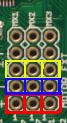
In the above image:
the Red pins nearest the tiny "1" are the VCC
the Blue pins are the Ground
and the yellow pins are the PWM
Next:
Grab your endstop wiring from the wiring kit.
we will be matching the wires up on the endstop wiring to the servo wiring as follows:
Red will be to VCC
Black will be to Ground
Blue will be to PWM
connect the wires using the means you believe proper, I used the spare pins provided in the kit to make a male plug for the female servo connector and made all the wiring changes there so that in case the servo ever dies i only have to replace the servo and plug it in instead of having to cut and resolder everything.
CAUTION
IF you get the polarity wrong you WILL burn up the control board inside the servo! DO NOT CONNECT SERVO WHILE THE PRINTER IS POWERED ON!
At this point you have a servo that will reach the hot end and will be properly wired and able to be plugged into the MX ports in the Motor_EXT pins.
Go ahead and plug it into the MX port of your choice.
Make sure the red wire on the extension is at the "1" pin. and the blue wire is on the 3rd pin.
on to the software.
The Guide(Software/Firmware):
At this point you should be somewhat following along with zennmaster's guide as well, as this post is a supplement to that guide for rambo specifics.
Open the rambo user guide to page 48-49, depending on the which MX pin set you chose you will need to get the PWM pin number for PA0 PA1 or PA2
they are listed on page 49 as either 22, 23, 24.
After downloading the current version of marlin you will need to open the pins.h file in your favorite text editor(i use notepad++)
press Ctrl+F and type in rambo and hit find. This will take you to the rambo section of the pins.h file.
you will need to paste the following into the pins.h file after #define LARGE_FLASH true
Code:#ifdef NUM_SERVOS #define SERVO0_PIN <servo PWM pin> //replace <servo PWM pin> with the corresponding MX pin #if NUM_SERVOS > 1 #define SERVO1_PIN -1 #endif #if NUM_SERVOS > 2 #define SERVO2_PIN -1 #endif #if NUM_SERVOS > 3 #define SERVO2_PIN -1 #endif #endif
If you have been following the zennmaster guide, as well you will have also enabled ABL and copied all of the i3V settign over to the configuration.h file as well. Once all of that is complete your servo will be working and you can move on to the part 3 of zennmaster's guide which will guide you through the process of retraction angles and offsets.
-
12-21-2014, 11:18 AM #2Engineer
- Join Date
- Nov 2014
- Posts
- 522
I may try to go into more detail later if its needed but for now I think this is pretty understandable and step by step.
-
12-21-2014, 07:29 PM #3Technologist
- Join Date
- Nov 2014
- Posts
- 138
Thanks. Bought the same servo and you. Right now am just preparing for a paint job on the frame.
-
01-15-2015, 02:03 PM #4Engineer
- Join Date
- Nov 2014
- Posts
- 522
So good news, in Marlin accepted my pull request to the development branch that adds notes for the Rambo Fan and best servo pins and Servo support to the Pins.h
So if you are pulling the most recent version of marlin you no longer have to add things to pins.h just change the servo0 if prompt to the pin you are using. :-)
-
01-17-2015, 12:51 AM #5Engineer
- Join Date
- Dec 2014
- Location
- Canada
- Posts
- 498
im using MX3 so my pin is 24
im confused as to what im changing to this
// servo support
#ifdef NUM_SERVOS
#define SERVO0_PIN 22 //motor header MX1
#if NUM_SERVOS > 1
#define SERVO1_PIN 23 //Motor header MX2
#endif
#if NUM_SERVOS > 2
#define SERVO2_PIN 24 //Motor header MX3
#endif
#if NUM_SERVOS > 3
#define SERVO2_PIN 5 //pwm header pin 5
#endif
#endif
-
01-17-2015, 05:40 AM #6Engineer
- Join Date
- Nov 2014
- Posts
- 522
Change 22 to 24
Thats it
If i have some time today i will update this to reflect the changes.Last edited by sniffle; 01-17-2015 at 05:55 AM.
-
01-17-2015, 08:47 AM #7Engineer
- Join Date
- Dec 2014
- Location
- Canada
- Posts
- 498
I keep getting a Endstop hits Z, message when im trying to manually control z height, and its not hitting anything
-
01-17-2015, 09:55 AM #8Engineer
- Join Date
- Nov 2014
- Posts
- 522
Check the zennmaster videos on youtube... There is an option in the cobfiguration.h to allow going below software endstops and the x y or z can become negative in value.
-
01-17-2015, 09:58 AM #9Engineer
- Join Date
- Dec 2014
- Location
- Canada
- Posts
- 498
i have entered my probe offset but now it wont compile
give me an error
This report would have more information with
"Show verbose output during compilation"
enabled in File > Preferences.
Arduino: 1.0.6 (Windows NT (unknown)), Board: "Arduino Mega 2560 or Mega ADK"
In file included from /Marlin.h:22,
from BlinkM.cpp:5:
/Configuration.h:447:9: error: floating constant in preprocessor expression
/Configuration.h:452:13: error: floating constant in preprocessor expression
/Configuration.h:456:9: error: floating constant in preprocessor expression
/Configuration.h:461:13: error: floating constant in preprocessor expression
these are my offsets
#define X_PROBE_OFFSET_FROM_EXTRUDER 51.5
#define Y_PROBE_OFFSET_FROM_EXTRUDER -8.6
#define Z_PROBE_OFFSET_FROM_EXTRUDER -10.4
here is also my endstop settings
can someon have a look over,
#ifndef ENDSTOPPULLUPS
// fine endstop settings: Individual pullups. will be ignored if ENDSTOPPULLUPS is defined
#define ENDSTOPPULLUP_XMAX
#define ENDSTOPPULLUP_YMAX
#define ENDSTOPPULLUP_ZMAX
#define ENDSTOPPULLUP_XMIN
#define ENDSTOPPULLUP_YMIN
// #define ENDSTOPPULLUP_ZMIN
#endif
#ifdef ENDSTOPPULLUPS
//#define ENDSTOPPULLUP_XMAX
//#define ENDSTOPPULLUP_YMAX
//#define ENDSTOPPULLUP_ZMAX
#define ENDSTOPPULLUP_XMIN
#define ENDSTOPPULLUP_YMIN
#define ENDSTOPPULLUP_ZMIN
#endif
// The pullups are needed if you directly connect a mechanical endswitch between the signal and ground pins.
const bool X_MIN_ENDSTOP_INVERTING = false; // set to true to invert the logic of the endstop.
const bool Y_MIN_ENDSTOP_INVERTING = false; // set to true to invert the logic of the endstop.
const bool Z_MIN_ENDSTOP_INVERTING = false; // set to true to invert the logic of the endstop.
const bool X_MAX_ENDSTOP_INVERTING = false; // set to true to invert the logic of the endstop.
const bool Y_MAX_ENDSTOP_INVERTING = false; // set to true to invert the logic of the endstop.
const bool Z_MAX_ENDSTOP_INVERTING = false; // set to true to invert the logic of the endstop.
//#define DISABLE_MAX_ENDSTOPS
//#define DISABLE_MIN_ENDSTOPS
// Disable max endstops for compatibility with endstop checking routine
#if defined(COREXY) && !defined(DISABLE_MAX_ENDSTOPS)
#define DISABLE_MAX_ENDSTOPS
#endif
// For Inverting Stepper Enable Pins (Active Low) use 0, Non Inverting (Active High) use 1
#define X_ENABLE_ON 0
#define Y_ENABLE_ON 0
#define Z_ENABLE_ON 0
#define E_ENABLE_ON 0 // For all extruders
// Disables axis when it's not being used.
#define DISABLE_X false
#define DISABLE_Y false
#define DISABLE_Z false
#define DISABLE_E false // For all extruders
#define DISABLE_INACTIVE_EXTRUDER true //disable only inactive extruders and keep active extruder enabled
#define INVERT_X_DIR false // for Mendel set to false, for Orca set to true
#define INVERT_Y_DIR false // for Mendel set to true, for Orca set to false
#define INVERT_Z_DIR true // for Mendel set to false, for Orca set to true
#define INVERT_E0_DIR false // for direct drive extruder v9 set to true, for geared extruder set to false
#define INVERT_E1_DIR false // for direct drive extruder v9 set to true, for geared extruder set to false
#define INVERT_E2_DIR false // for direct drive extruder v9 set to true, for geared extruder set to false
BTW my X and Y have reversed stepper plugs
-
01-17-2015, 10:11 AM #10Engineer
- Join Date
- Dec 2014
- Location
- Canada
- Posts
- 498
here is my current config h file for reference
Configuration.h

 Reply With Quote


QIDI Slicer "Plater" is...
04-12-2024, 02:21 AM in QiDi 3D Printer Forum