


Results 61 to 70 of 255
-
08-29-2014, 09:39 PM #61Engineer

- Join Date
- Jul 2014
- Location
- Eastern Colorado
- Posts
- 536
I finally received all the parts needed for the header fan/light hookups. I decided to go for a more "modular" approach. I purchased these www.amazon.com/dp/B00FH6UYLW and these www.amazon.com/dp/B00KWA1RJ6 . I cut the jumper wires in half, and used some of them to connect negative through the switch and positive from the power supply to the pin headers, and spliced others to the fan and light wires, to plug them into the pin headers. This way the only soldering I had to do was wire-to-wire, everything else was "plug & play". I cut up a Command adhesive strip to mount the headers below the RAMPS board. Sorry for the poor lighting in the image.
IMG_20140829_203539.jpg
-
09-03-2014, 11:09 AM #62Staff Engineer
- Join Date
- May 2014
- Location
- Highlands Ranch, Colorado USA
- Posts
- 1,437

NOISE AND VIBRATION REDUCTIONS
Several changes have been made to reduce vibrations and other noise sources from the printer. Almost every print can reveal new causes, depending on print sizes, travel speeds, etc.
OPERATIONAL CHANGES
Although I've made some mods to reduce vibrations, some of the improvements are just in how I use the printer.
Following clough42's recommendation of setting retraction speed to 10mm/sec had a side benefit of reducing noise considerably. I'm not sure if the extruder motor was skipping before or what, but 10mm/sec causes retraction to be smooth and quiet now.
FOLLOWUP COMMENT: After digging into motor capabilities and limitations, I've increased my retraction speed to 15mm/sec.
When I was using slic3r as my slicer, I learned to orient prints that have a lot of infill on the bed so I could set linear/rectilinear infill orientation angle to 0 instead of the normal 45 degrees. 45 degrees causes the X and Y motors to be alternatively stepped to accomplish the diagonal movement. 0 degrees allows linear/rectilinear infill to be accomplished with single-motor movements in the X-axis or Y-axis direction across the entire print. The first time I bumped into this with the long top-side spool mount brackets printed diagonally on the bed, I was very surprised in how much quieter the print went. Unfortunately, Cura forces all infill to be at 45 degrees, so I don't have that option when I'm using it.
PRINTER MODS
One of the more surprising vibrations I tracked down was on the RAMPS board. It turned out to be the two square yellowish plates (polyfuses) by the power entry block. They were touching, and would rattle under certain conditions. A dab of hot glue added between the two yellow plates eliminated that vibration.
The LCD has been pretty annoying. The mods thread and an earlier post here talk about reducing vibrations between the two boards in the LCD assembly. After that, I still found that under certain conditions the LCD assembly would vibrate within the rectangular hole of the wood frame. I added narrow strips of electrical tape to either the wood frame or the LCD boards where ever the display and wood were touching. No more vibrations there.
The fan on the hex hot end would occasionally vibrate against the hot end fan shroud. It's unfortunate that the provided fan shroud was designed with only two mounting holes for the fan. Rather than redesign the shroud, I added a thin silicone isolator for 40mm fans between the fan and the shroud.
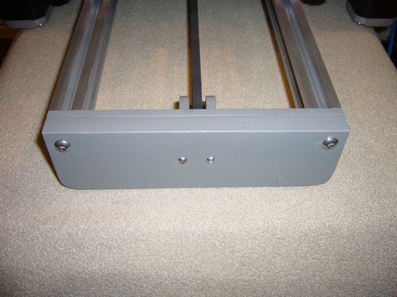
Another thing I noticed was that Y-axis travel was considerably noisier than X-axis travel. Maybe this should be expected to an extent since Y-axis noise can be potentially reverberated by the Y-bed, but I still wanted to see what I could to do to reduce it. First, the natural way to go about installing the Y-motor is to set it in the bracket and tighten it in place. I thought this could be leading to the motor vibrating against the bottom of the motor mount, so I added some silicone sheet material there as an isolator. This has to be pretty thin. Since I've got the motors that run hot, I wanted to use some high temperature material, and trimmed a piece from a silicone jar opener sheet even though it is a bit too thick. Fiberglass tape or silicone heatsink film would be good. In a pinch even electrical tape would likely be better than nothing. I also added isolator material to the face of the motor, but I'm not convinced that really helps. To minimize the possibility that the thin wood plates used to mount the Y-motor and Y-idler were reverberating with motor movements, I reinforced them with additional plates cut from 1/2-inch poplar, with holes drilled to match the ones in the original plates. I kept the plates as add-ons rather than replacements so that I could easily add or remove them. Besides, my glued-up frame components really didn't give me much choice.

Longer bolts were then used to pass through both the reinforcement plate and the original plate. The M5 bolts were 25mm, and the M3 bolts 30mm. I used button head for appearance. The original front plate had definitely flexed, since I could see the center of the thin plate pull forward as I tightened the two bolts on the idler bracket. Front view -
And rear view -
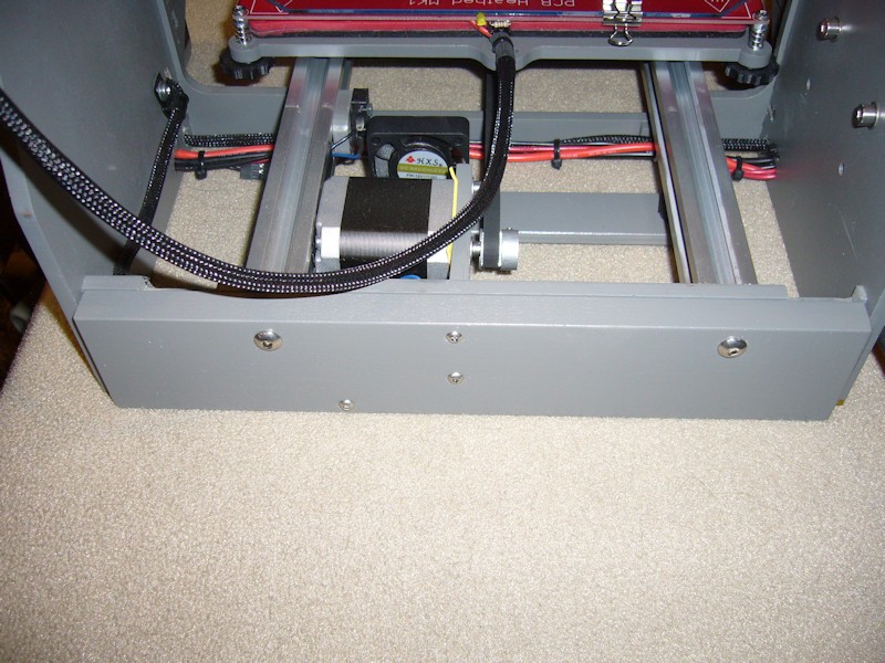
Combined, this made substantial reductions in noise related to Y-axis travel.
FOLLOWUP COMMENT: For those with 10 and 12-inch printers, note that the front and rear frame reinforcement approach was developed on an 8-inch printer. For the larger printers, it may be necessary to replicate any notches in the top of the original rear brace onto the reinforcement so that corner hardware on the Y-bed can clear the rear frame. This wasn't necessary on the 8-inch printer.
Ringing in the helical coil portion of the flexible Z-axis shaft couplers has been eliminated by the dampening effect of a few turns of clear tape added around the coiled part of the couplers.
FOLLOWUP COMMENT: The most significant improvement in noise reduction came later when I adjusted the stepper motor drivers by motor performance, not measured voltage. Set by voltage, I believe the motors are being driven harder than they have to be. Readjusting the drivers so that the motors function without skipping reduces the noise considerably.
OTHER
As of now, I haven't spent the money on the sorbothane feet. I've printed and installed clough42's adapters for them, but just using other adhesive foam I have seems to be working OK with the other reductions I've made. Note that the reinforcement plates added to the front and rear were notched on the bottom to accommodate the round adapters.
FOLLOWUP COMMENT: Sorbothane feet have been purchased and installed.
I've also seen the X belt flapping on the left-side of the X axis v-rails, but only on certain prints. It seems to take a pretty particular combination of carriage position and travel speed to lead to the flap, and it's a pretty low frequency noise. I've added one small piece of Velcro tape to the far-left inside of the v-rail. I don't want to add more throughout the v-rail that might catch on the x-carriage belt mount. In a future mod, I may try adding another of the printed belt guides to a longer bolt on the X-motor eccentric spacer wheel and go from there.
FOLLOWUP COMMENT: I later learned the frequent flapping of the left-side of the X-belt and occasional flapping at the rear of the y-belt could be managed as part of adjusting the stepper motor driver by operational use, not a fixed voltage. I just know the flapping went away when I lowered the drive setting some.Last edited by printbus; 04-30-2016 at 07:12 PM. Reason: clarified how adjusting stepper drivers eliminated belt flapping
-
09-08-2014, 11:10 AM #63Staff Engineer
- Join Date
- May 2014
- Location
- Highlands Ranch, Colorado USA
- Posts
- 1,437
MINOR FIRMWARE PERSONALIZATION
Normally, I'd refrain from making piecemeal firmware changes since it can lead to configuration control issues downstream when incorporating mainstream Marlin updates. I caved, however, and adjusted some of the installed firmware to better suite my liking. Here's a summary in case others might be interested in these straightforward changes as well.
I've enabled settings to be saved to the printer EEPROM IAW this thread - Makerfarm Calibration Thread of Grand Proportions
Although the setting can be saved in EEPROM now, I also adjusted the esteps per mm value in the firmware to a value closer to a better average from the calibration measurements I've performed. In the configuration.h file, this is accomplished by editing the 841 value in the #define DEFAULT_AXIS_STEPS_PER_UNIT {80,80,4000,841} statement. Mine changed to 900.
I opted to personalize the "MakerFarm I3 Ready." status message on the LCD. That was changed by editing the language.h file "MakerFarm" text in the #define MACHINE_NAME "MakerFarm" statement and the " I3 Ready." text in the #define WELCOME_MSG " I3 Ready." statement. My status line now defaults to "Printbus i3v ready". At the end of a print, I also have that restored to the printer by including an M117 Printbus i3v ready line as the last entry in my slicer end gcode. FOLLOWUP COMMENT: The approach to setting the machine name has changed in newer versions of Marlin.
I found the 15-second timeout on the LCD display to be too short. That was increased to 30 seconds by doubling the 15000 value in the ultralcd.h file #define LCD_TIMEOUT_TO_STATUS 15000 statement.
Some of the print cooling fans I've been experimenting with have exhibited a whine from the frequency of the PWM power RAMPS applies to control speed. I've eliminated this whine by uncommenting (removing the two // preface characters) the configuration.h #define FAST_PWM_FAN statement.
On occasion, I still get garbled data displayed on the LCD. I now reinitialize the LCD interface periodically following the simple firmware change described in thread Garbled LCD screens
I felt the Z axis speed when homing was slower than it had to be, especially if the X-carriage has a long ways to travel back to the bed. In configuration.h, I ended up doubling all three homing axis speeds by changing the #define HOMING_FEEDRATE {50*60,50*60,50,0} values to {100*60,100*60,100,0}. I've observed no issues with these increased speeds affecting the accuracy of the home process.
Finally, I thought X and Y axis movement was overly fast when commanding manual moves from the LCD or host software. In configuration.h, I reduced the #define DEFAULT_MAX_FEEDRATE {250,250,2,22} values to {150,150,2,22}.
FOLLOWUP COMMENT: Reflecting what was learned in research for http://3dprintboard.com/showthread.p...rtables-h-data, I've also changed configuration.h to specify Type 1 thermistors on both the bed and the hot end.
I'm still holding off on incorporating auto-leveling. As adjusted, the bed and the X/Y v-rails are true and stay that way. Once I've taken a minute or two to adjust the bed thumbwheels for any change in bed covering, I find no need to adjust leveling on an ongoing basis. Besides, I have something else in mind for the left side of the X-carriage and don't want to lose it to the leveling servo...Last edited by printbus; 11-01-2014 at 08:06 AM.
-
09-12-2014, 01:25 PM #64Staff Engineer
- Join Date
- May 2014
- Location
- Highlands Ranch, Colorado USA
- Posts
- 1,437
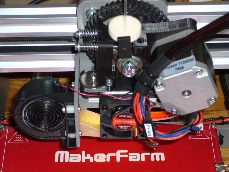
EXTRUDER REBUILD AND NEW PRINT COOLER (Part 1 of 2)
An unplanned softening of the extruder base gave me the opportunity to rebuild the extruder, rethinking some of it during the process.
EXTRUDER PRINTED PARTS
I had previously printed my replacement parts at 75% infill. That should provide a solid base that holds up to the stress of the motor bolts and the extruder mounting bolts. I also use fender washers and nylon locknuts on the extruder mounting bolts instead of the nut captures in the base.
For infill comparison, the base MakerFarm provided was likely printed at 25% infill based on Cura slicer weight estimates.
The shaft hole in the small extruder gear was presized with a 5mm drill bit. To ensure a true hole, a drill press was used.
EXTRUDER MOTOR
My i3v kit included CW type 42BHH48-050-24A stepper motors that generally run hot. In the rebuild, the extruder motor was replaced with a Kysan 1124090. Compared to the CW, it's nice having an extruder motor that doesn't even get warm. No more shroud or cooling fan on this motor. As a side benefit, I noticed the Kysan uses 22 AWG wiring. The CW motor was only 26 AWG. Less voltage drop in the motor wiring should maximize the power being applied to the Kysan motor.
FILAMENT ALIGNMENT TUBE
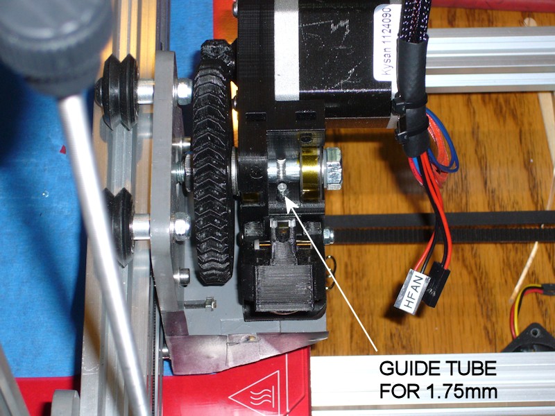
It seems like luck has always been required to successfully feed 1.75mm filament into the body of the hexagon hot end, likely because the feed hole at the bottom of the extruder base is large enough to also accommodate 3mm filament. I'd often have to use a flashlight and futz around with aligning the filament with the top of the deeply recessed hot end. To ease this, I've added a 25-mm length of 3mm OD aluminum tube to the extruder base feed hole below the hobbed bolt. The tubing I used (K&S 9802 from a hobby store) has 0.45mm wall thickness, so the tubing ID should be more than adequate to handle any normal 1.75mm tolerances that still fit the hot end. A small amount of flexible adhesive was used to ensure the tube remains in place during retractions and when swapping out filament. To feed filament, now I only need to get it into the top of the alignment tube, and the end of the aluminum tube is visible from above without using a flashlight.
FOLLOWUP COMMENT: I probably rate the filament guide tube mod as the second slickest mod I've incorporated into my printer, right behind the screw-adjustable Z-endstop approach. It is so much easier to feed filament now.
FOLLOWUP COMMENT #2: I don't remember who it was, but someone mentioned in another thread that a portion of an empty ink tube from a BIC-type pen also works as the alignment tube for 1.75mm filament.
HOBBED BOLT
I used a thin nylon washer combined with several thin 8-mm ID shims under the head of the hobbed bolt as required to optimize alignment of the cut in the hobbed bolt with the filament channel in the extruder assembly. The shims I used were from a Calandra Racing Concepts axle shim kit #4738.
Many people use the Gregg's Accessible Extruder without issues, but I just don't get part of the mechanical design. To improve the fit and minimize radial play of the hobbed bolt in the bearings, I wrap the bearing areas of the hobbed bolt with some kapton tape. Seems like a good thing, right? The problem is that the inner races of the hobbed bolt bearings rub against the plastic of the extruder base. Leave the hobbed bolt too loose and you might have axial play in the bolt. Too tight and the inner bearing races will bind on the extruder base, and if the hobbed bolt isn't loose in the bearings (like if the bolt is wrapped with tape so it is snug in the bearings), there'll be drag on the hobbed bolt rotation. Does the Greg's design assume the hobbed bolt will just spin inside the inner bearing race? If so, why were bearings even used? I don't see an easy solution here, but the base design could at least have a bit of a recess to provide clearance for the inner races of the bearings.
FOLLOWUP COMMENT: I believe the original design may have intended for large-id washers to be be used between the base and the bearings. Spacer rings are included in some Thingiverse versions of the Greg's Wades extruder such as this one - http://www.thingiverse.com/thing:18379.
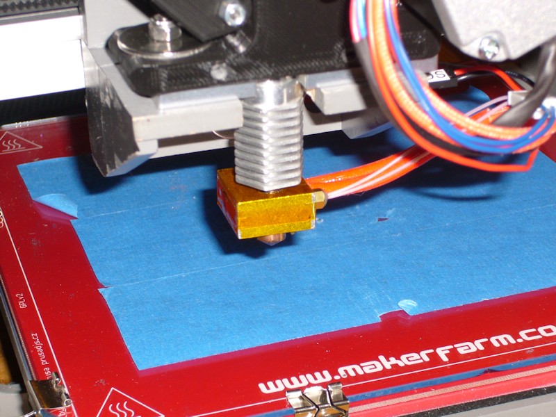
HEXAGON HOT END ASSEMBLY
I thought I had previously misthreaded the aluminum block on my hex hot end, so I bought a 20-mm block and 20-mm heater to use in the rebuild. During reassembly, I essentially applied part of Tom's E3D v6 assembly instructions, in that the tip is NOT tightened up against the aluminum block. A benefit of this on the hex hot end is the hex heatsink can be oriented how you want it, and the tip is then tightened up against the barrel of the heat break. I also wrapped the aluminum block in kapton to provide some insulation from airflow caused by the heatsink cooling fan and from the print cooler. I don't like the idea of a thick insulator on the top of the block since it could restrict airflow below the important lowest fin on the heatsink. Multiple layers of kapton were also added to the flat top end of the hot end to ensure a snug fit when the extruder is bolted onto the carriage. These layers were trimmed to clear the filament feed hole.
FOLLOWUP COMMENT: The tip was retightened when it was brought up to temperature the first time.
HEXAGON HOT END COOLING SHROUD
In previous mods, I've already been cutting out the flat part of the shroud that sits above the aluminum block of the hexagon hot end, since it'll likely melt away anyway. In the rebuild, I also added some "wings" to the rear of the shroud to help ensure airflow is forced onto the hot end heatsink rather than just bypassing around it. I cut the wings from some thin printed PLA sheet and attached them using medium-CA.
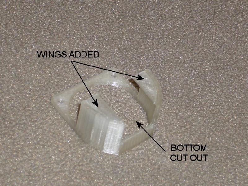
FOLLOWUP COMMENT: I later migrated to a custom design for the shroud discussed in post New Approach for the Hexagon Hot End Shroud.
FOLLOWUP COMMENT: Since I mention it in another thread, I'll add that there was another problem I was trying to solve in the extruder rebuild. Since resolving or minimizing noise sources earlier, I was left with an annoying creak somewhere in the extruder. Using a hose as a listening tube, it seemed like the noise was coming from the area of the hobbed bolt or the filament idler. I actually had the extruder apart multiple times to try to eliminate it. I ultimately applied everything I could think of in a final build, including the use of new bearings on the hobbed bolt, new kapton tape on the hobbed bolt, lubricating where the bearing inner races can ride on the plastic of the extruder base, etc. Somewhere in the final attempt when the new motor was also installed the creak has in fact been eliminated.Last edited by printbus; 05-03-2015 at 10:51 AM. Reason: migrated to offsite image storage due to 3DPrintBoard issues
-
09-12-2014, 01:49 PM #65Staff Engineer
- Join Date
- May 2014
- Location
- Highlands Ranch, Colorado USA
- Posts
- 1,437
EXTRUDER REBUILD AND NEW PRINT COOLER (Part 2 of 2)
PRINT COOLER
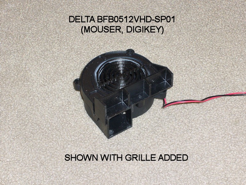
FOLLOWUP COMMENT: According to an end-of-life notice from DigiKey, the manufacturer has transitioned the specific fan suggested here to obsolete status. I believe Mouser has already dropped it from their catalogue. DigiKey still had stock the last time I checked. It may not be available for future readers of the thread. Unfortunately, the fan was used because of its very unique mounting provisions, and I am not aware of a suitable substitute.
Since putting a focusing shroud on an axial fan creates backpressure that usually reduces fan airflow, this time I wanted to use a radial blower for the print cooler. After considering several concepts, I opted to go with a Delta BFB0512VHD-SP01 blower mounted onto the left side of the X-carriage. I added a grille to the blower intake by aborting a print of http://www.thingiverse.com/thing:401935 as the ring part was done, trimming off the part of the rings that didn't fit into the opening of the blower.
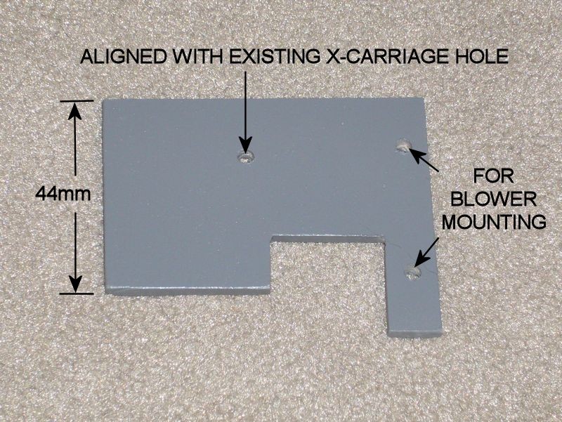
I fastened the blower to a 64-mm by 54-mm piece of 1/8-inch hobby plywood that attaches to the existing X-carriage, replacing the original bolt on the left side of the carriage with a longer one. This specific blower is unique in that it has mounting provisions on the face with the blower opening, providing a straight shot from the blower to the print. One advantage of having the blower on the separate bracket is that the connectorized print cooler assembly can be easily added to or removed from the printer.
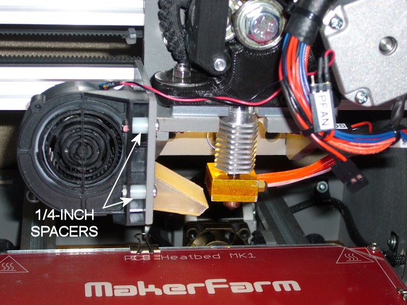
The blower is located forward enough so that the blower outlet clears the angled sidewall of the X-carriage, and located just high enough to provide binder clip clearance above the print bed glass. A simple duct inserted into the outlet of the blower helps keep airflow off the hot end. The adapted version of the final duct I'm using is http://www.thingiverse.com/thing:461014. The duct is just press fit to provide some adjustment to the airflow angle, and to allow the duct to be swapped out without a lot of fuss.
Especially combined with a straight-shot duct (no right angles or rotational vortex to worry about), this is a very effective blower. Cooling is very adequate with the fan only running in the 10% range. At that speed, the audible whine from the low frequency Marlin uses on the fan PWM overpowered the low blower noise. This was resolved by a minor firmware change to have Marlin use the higher frequency fan PWM (see MINOR FIRMWARE PERSONALIZATION). The airflow is also focused and linear. At 100% blower speed, air from the blower can be felt several feet from the printer.
Note that the blower used is a 4-wire type. The red and black wires are wired to RAMPS D9. The other two wires aren't used. I cut them off and insulated the cut ends with small heatshrink tubing.
FOLLOWUP COMMENT: On large, straightforward prints where cooling won't be an issue, I've been running the blower at 10%. On more complex prints, I'll let Cura set the print speed between 10% and 25%. On really complex things, I'm finding it best to not have Cura control the fan speed and I'll do it manually through Repetier-Host. That way I can increase the speed to as much as 100% if I sense the need to for a bit, or I can back it down if I see the blower dropping the hot end temperature too much. When cooling is enabled in the slicing, Cura apparently sets the fan speed on every layer, so trying to manually override the temperature with Repetier-Host only works for the balance of that layer before the fan speed is set again in the gcode.Last edited by printbus; 04-22-2016 at 07:37 AM. Reason: fan is obsolete
-
09-14-2014, 05:09 PM #66Staff Engineer
- Join Date
- May 2014
- Location
- Highlands Ranch, Colorado USA
- Posts
- 1,437
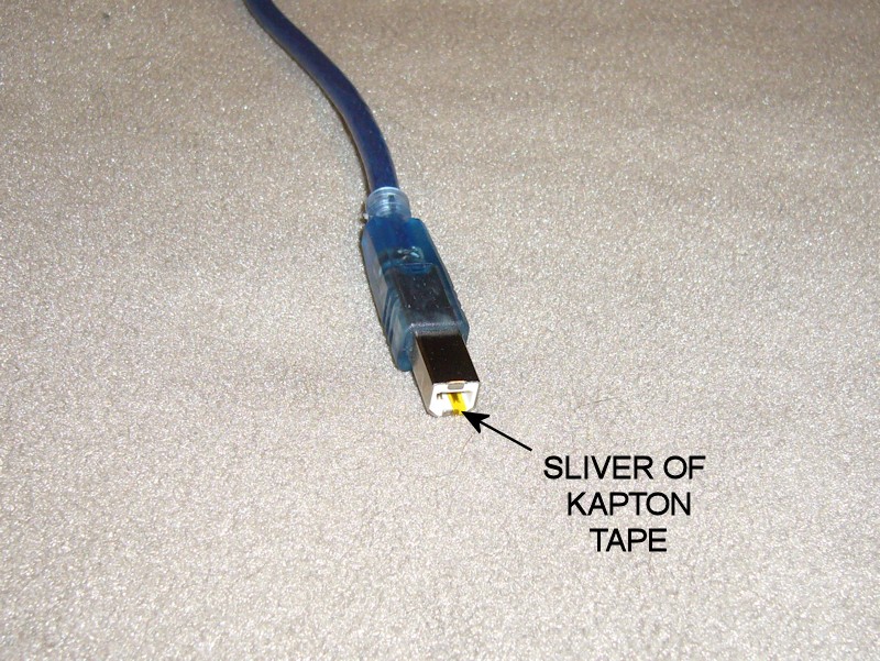
DISABLING POWER FROM USB
I've been one of those annoyed with how RAMPS stays powered up when the printer power supply is turned off but the USB cable is plugged into a host computer. A review of the MEGA2560 card indicated there's no jumper or other built-in means to change this. The board is designed so that if there is power on the USB connector, it will be used.
There's still a pretty easy fix for this - use a narrow strip of kapton tape to cover the 5V contact in the USB Type B connector that plugs into the RAMPS board.
Some USB interface designs require the 5V from the USB for at least the initial connection. The testing with the Arduino-type Mega2560 board in my i3v went OK without 5V being applied to the USB at all.
If you perform the mod, it might be a good idea to tag the cable as being modified in case the cable is reused for some other application later.
DISCLAIMER: The Arduino reference design for the Mega2560 board connects USB 5V to the UVCC pin on the ATMEGA16U2 USB interface chip. That pin no longer gets 5V with this mod, and the ATMEGA16U2 datasheet doesn't provide enough detail to understand what, if any, ramifications this may have. Also note that in a later post, a user observed erratic operation of his Auto Bed Leveling (ABL) servo with 5V removed from the USB cable, likely because the 12V-to-5V voltage regulator on the Mega2560 can't handle the extra 5V load from the servo. Implement this mod at your own risk.Last edited by printbus; 05-03-2015 at 11:04 AM. Reason: migrated to offsite image storage due to 3DPrintBoard issues
-
09-22-2014, 01:10 PM #67Staff Engineer
- Join Date
- May 2014
- Location
- Highlands Ranch, Colorado USA
- Posts
- 1,437
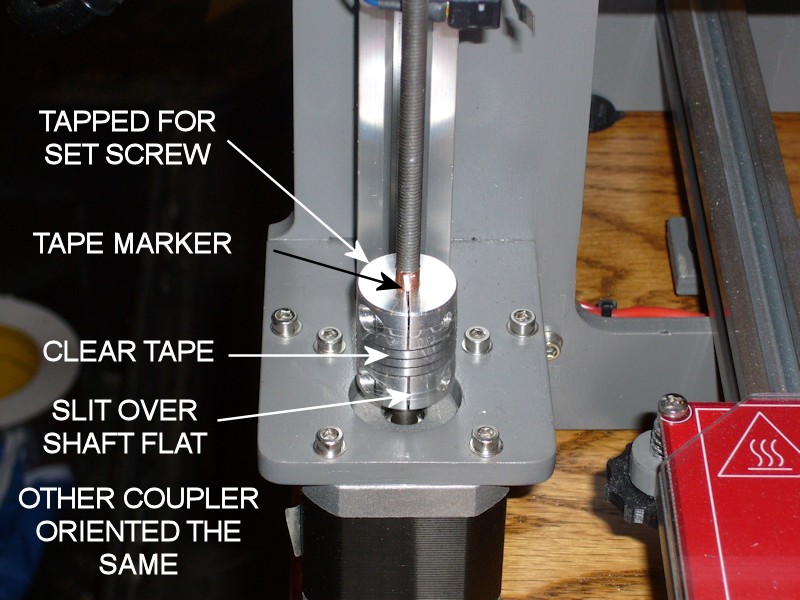
TWEAKS TO THE COUPLERS ON THE Z-AXIS RODS
During bed leveling after the recent extruder rebuild, I noticed one of the threaded rods was slipping inside the spiral shaft coupler. Things have been printing fine, and I'm not sure how long this has been loose. Things were likely printing fine because of the way I had aligned the X-axis as part of the original build.
When I built the printer, I had already purchased the "split collar" type of couplers before I learned there is another type that uses two pairs of set screws to grab the shafts. Now I wish I had purchased the set screw type instead. Sticking with what I had, I made some improvements.
- I tapped both couplers for an M3 x 6mm set screw as a secondary grip on the shafts.
- I made sure the two couplers were oriented the same way. I hadn't done this before, and one coupler was inadvertently upside down from the other. They'll work fine either way, but having them oriented the same way makes it easier to tell at a glance whether one is unintentionally rotated off from the other.
- This time I think I put more attention to how the clamping end is oriented over the flat of the motor shafts. Now the open slit is right above the flat; tightening the clamping screw should provide the most grip on the motor shaft.
- Before tightening the threaded rods in the couplers, I made sure the two motors shafts were rotated so the shaft flats (and couplers) are rotated to the same position. Again, this will just make it easier to see if one motor is off from the other.
- After rechecking alignment between the X-motor and X-idler plates and tightening the couplers onto the threaded rods, I added narrow slivers of tape onto the threaded rods. The slivers of tape are placed in line with one of the cuts in the coupler ends to also serve as a quick-glance indicator that the rods are slipping in the coupler. I left enough of the foil tape wrapped around the threaded rods to stick the tape sliver to, although this would mean I wouldn't notice the threaded rod slipping inside the tape.
- I've had a high frequency whine often present when lowering the X-carriage down to the print bed. This was found to be coming from the spiral winding of the shaft couplers. I added two turns of clear tape over the spiral part of the couplers to provide a dampening effect that has eliminated the whine.
Last edited by printbus; 05-03-2015 at 03:25 PM. Reason: migrated to offsite image storage due to 3DPrintBoard issues
-
09-30-2014, 09:44 PM #68Engineer-in-Training
- Join Date
- Jul 2014
- Posts
- 204
Kevin - I tried the usb 5V isolation thing and got erratic operation of my ABL servo. the failure went away after removing the kapton from the connector. Does it make sense that removing that source of 5V might interfere with somethign in the RC servo section of the board?
-
10-01-2014, 07:44 AM #69Staff Engineer
- Join Date
- May 2014
- Location
- Highlands Ranch, Colorado USA
- Posts
- 1,437
Interesting. It could be that there IS a connection. Here's my theory - Originally Posted by TopJimmyCooks

5V power for the MEGA2560 board, RAMPS (mainly any servos connected to it) and the LCD panel can normally come from either the USB port or a fixed voltage linear regulator on the MEGA2560 board. With no 5v in the USB cable, 5v power will have to come from the fixed regulator on the MEGA2560 board. To provide maximum torque throughout the desired movement, RC servos typically operate through application of a series of short pulses of power to the servo motor. Each one of these pulses is going to draw a surge of current from the regulator, with the amount of surge dependent on the actual servo being used and the amount of mechanical load on the servo. It could be that these surges are more than the fixed regulator can handle. The other possibility is that there's a power dissipation issue with the voltage regulator supplying 5V for the servo(s) connected to the RAMPS board. Either could cause dropouts in the 5V output that could lead to erratic operation of the MEGA2560, the servos, or the LCD panel.
It could be that there are multiple factors involved. For example, perhaps there's only a small drop in the regulator voltage, but that is combined with voltage drop in the lengthy wiring required to get 5V to the ABL servo.
I'm not sure having a servo that moves too far as mentioned in your original thread would be a symptom I would expect, but who knows. I'll add a cautionary note regarding ABL to the post suggesting the USB cable mod.
FOLLOWUP COMMENT: The Power Supply section of http://reprap.org/wiki/RAMPS_1.4 does imply that there are concerns powering servos from the Arduino (MEGA2560) unless you're running the Arduino directly from a 5V supply or USB power. This would mean you have to also be wary about using a printer with ABL standalone, when no computer is connected to provide the additional 5V power needed for the ABL servo:"The 5V pin in that connector on RAMPS only supplies the 5V to the auxiliary servo connectors. It is designed so that you can jumper it to the VCC pin and use the Arduino's power supply to supply 5V for extra servos if you are only powered from USB or 5V. Since there is not a lot of extra power from the Arduino's power supply you can connect it directly to your 5V power supply if you have one."FOLLOWUP COMMENT #2: For the technically curious... The vague "...not a lot of extra power from the Arduino's power supply" statement in the wiki caused me to look at that some more. Per the Arduino baseline, the fixed regulator on the MEGA2560 is an ON Semi NCP1117ST50T3 part. Calculating the maximum power dissipation allowed in a linear regulator is always tricky, since you're having to estimate the design's ability to dissipate heat away from the part. For the SOT-223 regulator package being used here, the datasheet does have Figure 21 that shows how much power dissipation is acceptable for a given square of 2-ounce copper plane around the part. The graph tops out at just over 1.4 watts; let's take that as a maximum amount of power we would want to see in the printer application even though the copper on the board isn't exactly a square, we don't know the copper thickness, the RAMPS board is going to limit airflow, etc. With the printer not doing anything, I measure 140mA of 12V current going into the MEGA2560 board, and this should equate to the current flowing through the 5V regulator. So, without an ABL servo the power dissipation in the 5V regulator is already just about a watt. The math is P=V*I or (12-5)*0.14=0.98 watts. This is already well into our maximum. Using our notional 1.4W limit on the power dissipation, the maximum amount of current we could draw is I=P/V, or 1.4/(12-5)= 0.2 amps. This is only 60 mA above what I've already measured. Whatever margin the MEGA2560 board had in 5V regulator capacity is likely considered used up by the LCD smartpanel. This again emphasizes that those with an ABL servo may not want to operate the printer, or at least may not want to do a lot of bed leveling servo movement, without power being applied by USB or they risk overheating the 5V regulator. The saving grace is that bed leveling isn't a forever thing. The trick would be to get extra load from moving the ABL servo over quick enough.
Last edited by printbus; 10-01-2014 at 08:12 PM.
-
10-01-2014, 06:00 PM #70Engineer
- Join Date
- Jul 2014
- Location
- Eastern Colorado
- Posts
- 536
Sounds like a good argument for engaging the probe servo only once at the beginning of ABL, and again at the end, instead of at every probe point.

 Reply With Quote


Extruder not feeding during print,...
Yesterday, 01:59 AM in Tips, Tricks and Tech Help