


Results 51 to 60 of 255
-
08-10-2014, 09:32 PM #51Engineer

- Join Date
- Jul 2014
- Location
- Eastern Colorado
- Posts
- 536
I got my heatbed with my MakerFarm i3. I didn't even know there should have been an LED there.
Last edited by AbuMaia; 08-10-2014 at 09:34 PM.
-
08-10-2014, 09:47 PM #52Staff Engineer
- Join Date
- May 2014
- Location
- Highlands Ranch, Colorado USA
- Posts
- 1,437

I assume the i3 has the same heat bed as the i3v - a MK1? "Should have been" is a bit strong. MakerFarm simply opted to not bother having people install the LED parts on a standard heat bed designed to include them. "Can be there" is more accurate. I saw the pads for them on the heat bed I got, and went for it, using parts I had in my part bins. Again, having the LED really isn't that important. Originally Posted by AbuMaia

Last edited by printbus; 09-22-2014 at 01:37 AM.
-
08-12-2014, 10:08 PM #53Engineer
- Join Date
- Jul 2014
- Location
- Eastern Colorado
- Posts
- 536
Could you post more details about this? Originally Posted by printbus
-
08-13-2014, 07:47 AM #54Staff Engineer
- Join Date
- May 2014
- Location
- Highlands Ranch, Colorado USA
- Posts
- 1,437
Here's an additional picture that didn't make the picture limit for the original post. A pair of heavier gauge wires from the power supply is fanned out to individual pins in a 5x2 configuration socket header - like you would use to plug onto rows of pins on a circuit board. Wire-wrap length header posts are broken into two pins each and used to provide connection between the 5x2 header and individual socket headers for each fan, etc. Wire wrap length posts are used since they are long on both sides of the plastic block holding the pins. A bit of CA glue can be used to attach the header post part to the connector going off to wherever. This isn't the most elegant, but I wanted something that was quick and easy to change connections at and had to be made from parts I had on hand. I didn't want to wait another week for parts to arrive before I could power up. Originally Posted by AbuMaia
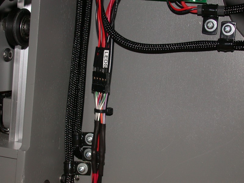
I'm always short on the socket contacts for these connectors. On a couple of things I've since added, I drilled out the holes in the 2-pin shrouds a bit so wires could pass through them, carefully soldered the wires directly to the short side of standard circuit board length header posts and then slipped the shroud down to cover the solder connections. A dab of glue keeps the shroud in place.Last edited by printbus; 05-03-2015 at 07:37 AM. Reason: migrated to offsite image storage due to 3DPrintBoard issues
-
08-13-2014, 10:53 AM #55Student
- Join Date
- Aug 2014
- Posts
- 25
is there in cura settings for the 10" i3v that i can jut load in?
-
08-13-2014, 12:33 PM #56Staff Engineer
- Join Date
- May 2014
- Location
- Highlands Ranch, Colorado USA
- Posts
- 1,437
No, but I wouldn't let that scare you away from trying Cura. IIRC, there's only four areas where settings are made. File | Machine Settings is where you'd set the size of your print area, type of G-code (set it to RepRap), etc. The Basic tab is where parameters are adjusted for almost every print - temperatures, print speed, etc. The Advanced tab has more settings that you'll likely only adjust once-in-awhile, such as first layer details. Settings under Expert | Expert Config allow you to tailor the support structure, raft, brim, etc. for when those options are enabled on the Basic tab. Originally Posted by nefiwashere
Other than Machine Settings, the only thing I remember really feeling the need to initially tweak was the retraction speed and distance under Advanced. Mine is set to 10mm/sec speed and 1.0mm distance. As clough42 has educated us, the MakerFarm extruder motor works better with a slower retraction speed, and we don't have a Bowden setup so the default of 4.5mm retraction distance is excessive for us.
Ultimaker has an on-line manual for Cura that walks through what you need to do for your "first print" with it. That'd be a good place to start. The manual is focused on those with an Ultimaker printer, but they do have info on how to use Cura with non-Ultimaker printers.
-
08-13-2014, 07:39 PM #57Engineer
- Join Date
- Jul 2014
- Location
- Eastern Colorado
- Posts
- 536
Thanks. I think I may emulate that setup, with two header sockets, though. I currently have two switches on my printer, one for fans and one for lights, and this header socket idea will make connecting fans and lights easier, as well as leaving an open, easily-accessible place to add more if needed, as you said.
-
08-13-2014, 08:12 PM #58Staff Engineer
- Join Date
- May 2014
- Location
- Highlands Ranch, Colorado USA
- Posts
- 1,437
Sounds like a plan. Another thing I liked about the header approach is that any extra, unused connections were well protected. No exposed screws on a terminal board, etc. Originally Posted by AbuMaia
Last edited by printbus; 09-22-2014 at 01:39 AM.
-
08-22-2014, 03:30 PM #59Staff Engineer
- Join Date
- May 2014
- Location
- Highlands Ranch, Colorado USA
- Posts
- 1,437
Y-MOTOR COOLING FAN
On the i3v, the Y-motor is pretty boxed in. I found it easy to add a small fan to provide some airflow to cool it down. A strip of 1/4 x 1 inch hobby plywood was attached to the bottom of the Y-bed v-rails using M5x30 button-head bolts, M5 nut plates, and 5.5mm ID x 20mm spacers derived from http://www.thingiverse.com/thing:5314. A 40mm fan was then hot-glued to the plywood. A printed design could do the whole thing and have mounting holes for the fan, but this was quicker. Using 20mm spacers, the top of the fan will be flush with the top of the Y-bed v-rails, so clearance is OK. I'm using one of the 40mm fans from MakerFarm. It doesn't take much airflow to make a big difference in the motor temperature.
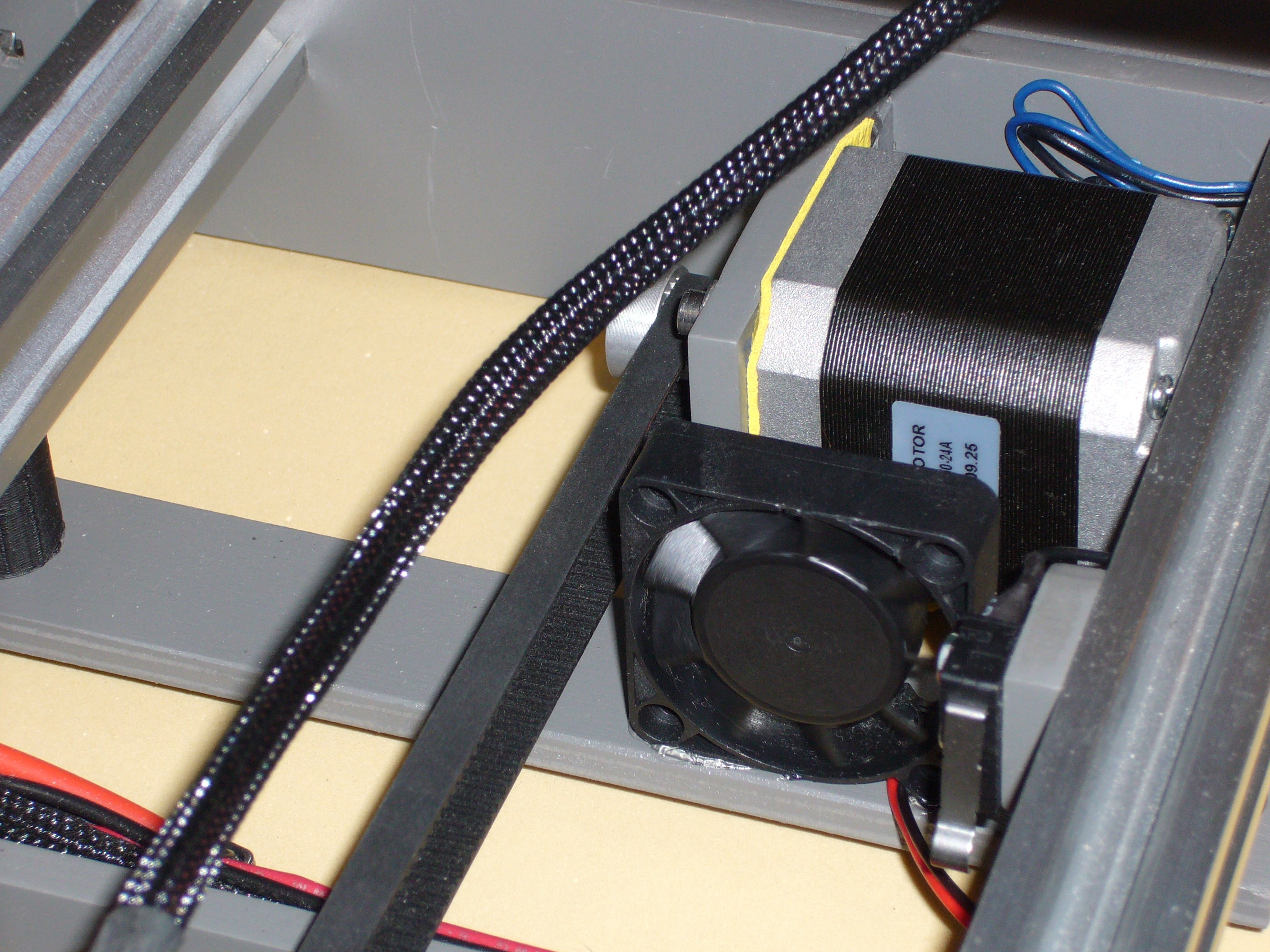
You wouldn't want to bring the fan forward much more than I show it or you'd need to watch for conflict with the belt bracket on the bottom of the Y-bed as the bed slides rearward. The picture shows my relocated position for the Y endstop switch; that isn't the normal location.
FOLLOWUP COMMENT: I have the motor type that runs hot. Cooling of the Y-motor and other stepper motors may not be required on all kits.Last edited by printbus; 05-03-2015 at 10:32 AM. Reason: migrated to offsite image storage due to 3DPrintBoard issues
-
08-25-2014, 09:00 PM #60Staff Engineer
- Join Date
- May 2014
- Location
- Highlands Ranch, Colorado USA
- Posts
- 1,437
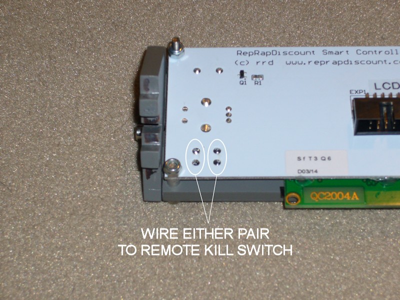
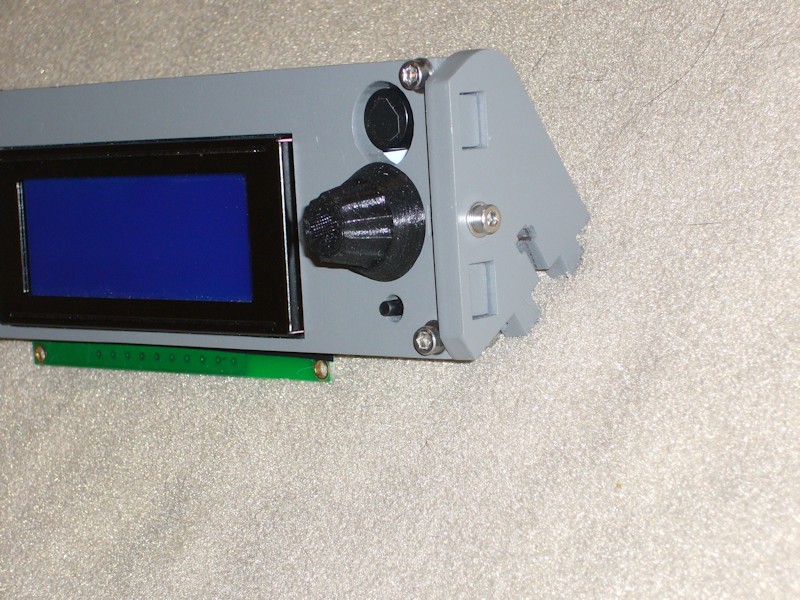
IMPROVED KILL SWITCH
I realize the RAMPS board has a reset button that can shut the printer down, but if some problem is underway I don't want to have to reach around the printer and find it. Cutting power seems to take a while. One option would be to piggy-back a remote switch to the existing reset switch, but I figured I would see what I could do to improve access to the STOP button on the LCD panel. For the unaware, that's wired into RAMPS as the Marlin kill switch. It's not very usable in the i3v frame since the button is recessed below the top of the wood holding the LCD panel. One option would be to glue some extension on the button stub. Another option would be to piggy-back wiring to another button added somewhere more accessible.
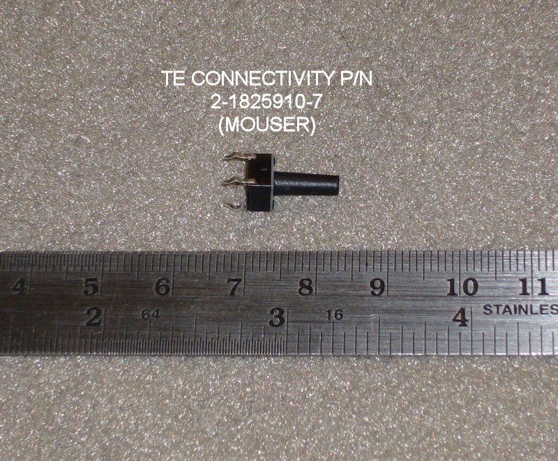
I also have some of the same 6mm square type pushbuttons in my parts bins that have taller buttons. They're available in various heights - the ones I have are 13mm from base of the switch to the top of the button. One of these could replace the existing switch.
I opted to go for the clean switch replacement solution that doesn't require drilling holes, adding wiring that might pick up noise, etc. Two of the switch pads are soldered to the ground plane on the board, making desoldering a bit tricky. The button sticks up above the wood panel now by about 2.5mm. It's definitely accessible without sticking up so high that it's likely to get pressed accidently. I'm not a fan for the entire kill action Marlin takes when the button is pressed, but I'll deal with that later. I would prefer for the status screen to keep updating so I could monitor cool-down temperatures.
Last edited by printbus; 05-03-2015 at 10:35 AM. Reason: migrated to offsite image storage due to 3DPrintBoard issues

 Reply With Quote


Extruder not feeding during print,...
Today, 01:59 AM in Tips, Tricks and Tech Help