


Results 31 to 40 of 255
-
06-03-2014, 07:23 AM #31Super Moderator

- Join Date
- Apr 2014
- Location
- Lone Star State
- Posts
- 2,182
I have a couple of LED's embedded into my extruder to do the same thing. But they burned out. They still light up but are not bright enough to serve any purpose now. I like the light strip idea. I think I'll go scrounge on eBay and see if I can find something suitable for my setup!
-
06-03-2014, 07:36 AM #32Engineer-in-Training
- Join Date
- Mar 2014
- Location
- USA
- Posts
- 388

Thanks very much for the pictures guys! They look great, I think I'm going to do that with mine now and will post pictures! No more flashlights for me haha
-
06-04-2014, 05:07 PM #33Staff Engineer
- Join Date
- May 2014
- Location
- Highlands Ranch, Colorado USA
- Posts
- 1,437
WIRE ROUTING (PART ONE)
Although there are a few things I'd likely do different, I'm pretty happy with how the wiring and cable routing turned out.
FOLLOWUP COMMENT: In response to issues others have had in understanding how to wire the heat bed relay, I've tried to provide some detail in thread Clarifying i3/i3v heat bed and heat bed relay wiring
Materials Used
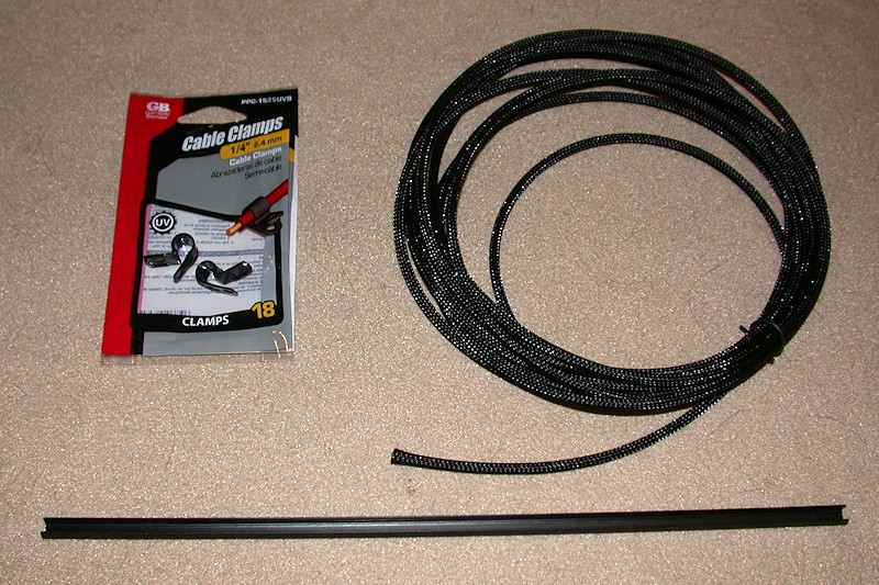
In addition to zip ties, I used (mostly 1/4-inch) expandable sleeving and a number of cable clamps to attach most of the wiring. Anyone who has used the expandable sleeving knows how frustrating it can be since it tends to unravel as soon as you cut it and try to feed anything through it. For this build I used "clean cut" sleeving I found on eBay that is a lot easier to work with. I also had obtained some aluminum rail slot covers from Openbuildpartstore. In addition to possibly being used for decoration, the slot covers can be used to create a wire raceway in the aluminum rails.
Every wire was custom fit to length, cutting off the connector and splicing it back on as required. I could have crimped new connectors on instead of splicing, but that would have required a lot of new contacts that I didn't have. Besides, almost all the heatshrink covered splices are now hidden inside the sleeving.
AC Power Switch
I added a push on/push off type power switch to the front of the printer.

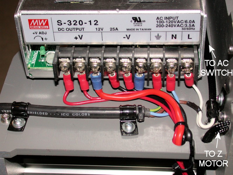
Power Supply Terminal Block
The power supply had three 12V and three return screws, so I routed three pairs of wires from the power supply to the other side of the printer. Heavy #14 wires were used for sourcing power to the heat bed relay. A dedicated pair of #18 wires provides power to the RAMPS board. An additional #18 pair fans out to low current loads like cooling fans and the LED lighting.
My power supply didn't come with any type of protective cover for the terminal block, so the AC connections are exposed. With time, I'll look into printing something to use.
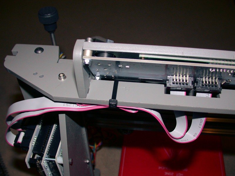
LCD Ribbon
I simply folded the excess ribbon from the LCD display and tied it to the upper member of the frame behind the LCD.
FOLLOWUP COMMENT: In the later GARBAGE DATA ON LCD DISPLAY post, I add a zip tie loop to pull the ribbon cables tight to the frame, away from the noise-laden bundle of wires from the X carriage that gets looped over the top of the printer. This helps reduce noise coupling into the LCD ribbon cables and messing up the screen.
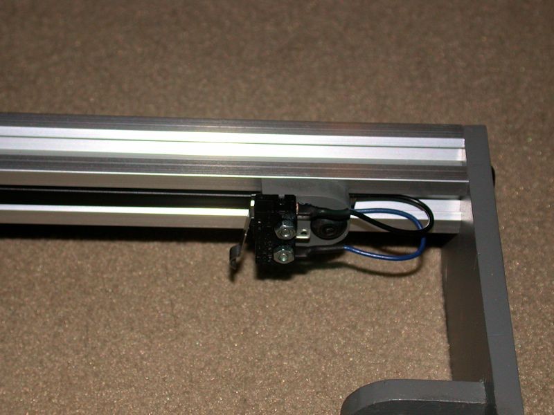
Y endstop switch wiring
Here I took advantage of the side channel of the aluminum rail and routed the wires through it. Wires are held in place behind a section of the black slot cover that was cut to fit. These wires get bundled with the wires from the Y motor at the back of the printer.
More routing info to follow... I've used up the five-pictures-per-post limit.Last edited by printbus; 05-03-2015 at 07:10 AM. Reason: migrated to offsite image storage due to 3DPrintBoard issues
-
06-04-2014, 05:21 PM #34Staff Engineer
- Join Date
- May 2014
- Location
- Highlands Ranch, Colorado USA
- Posts
- 1,437
WIRE ROUTING (PART TWO)
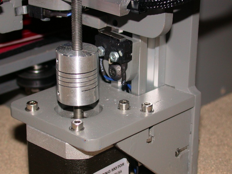
Z endstop switch wiring
Wires for the Z endstop switch were just dropped through the aluminum rail where they are bundled with the Z motor wires.
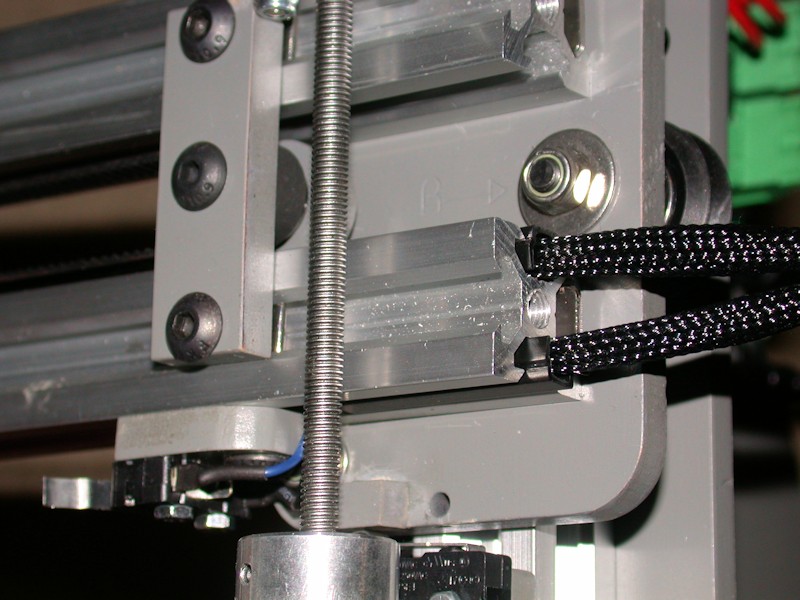
X Motor wiring
I fed the X motor wires to the other side of the printer through the top side channel in the lower X axis rail. A cut-to-fit slot cover keeps the wires in place. Sleeving extends from the motor to a few inches inside the rail.
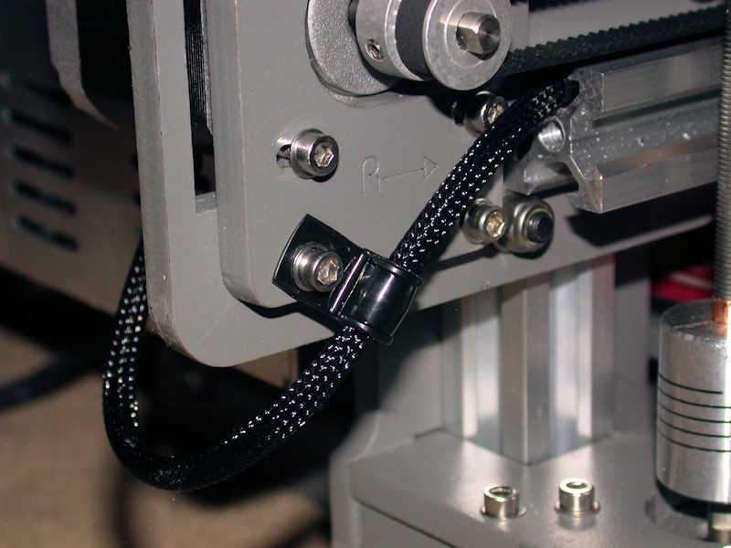
X endstop switch wiring
Other than adjustment access, there's nothing magic about the X endstop switch being on the top side of the X axis. For the cleanest wire routing, I moved it to the bottom and fed the wires to the end of the rail using the lower side channel. The X endstop wires and the X motor wires combine into a single bundle that loops around to the back of the printer. Note that moving the endstop switch required the switch to move to the other side of the endstop block.
FOLLOWUP COMMENT: After increasing the length of the notch in the endstop bracket, moving the X endstop switch underneath also allowed the switch to located a bit more to the right than would have been possible up on top. This was helpful in working to achieve the full 200mm printable area in the X direction.
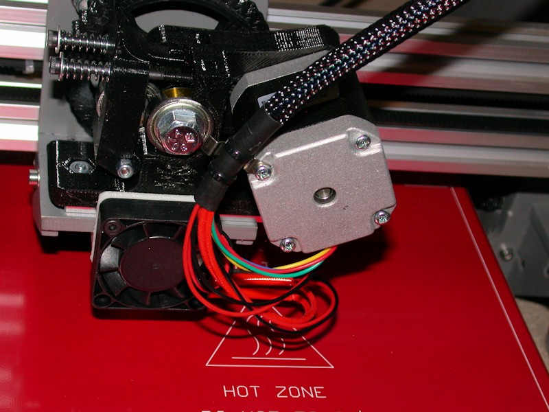
Extruder wiring
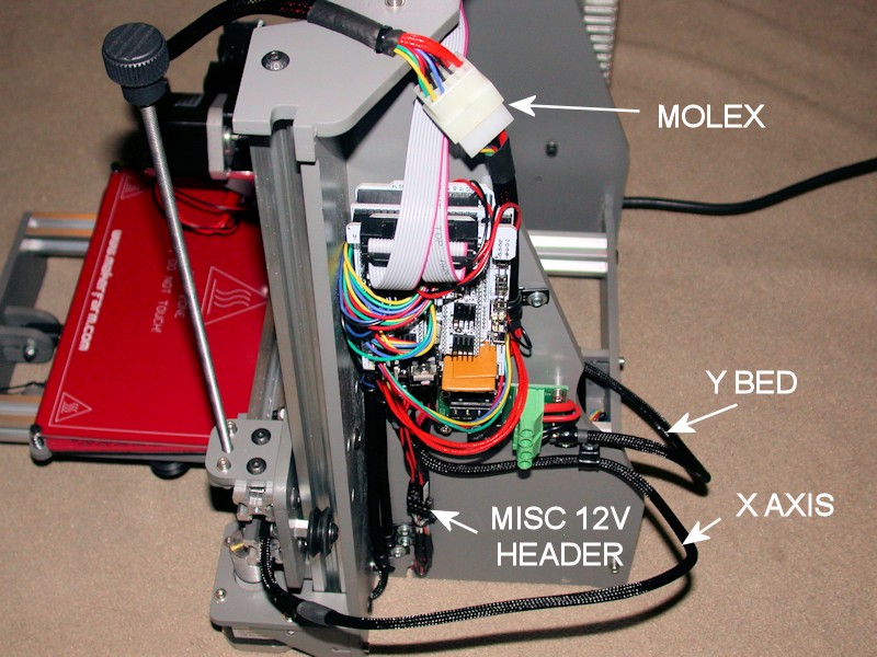
I used 3/8-inch sleeving over all the wires that are attached to the X carriage since 1/4-inch would have been a tight fit. The bundle is attached to the extruder motor using what I think is a spring contact from an old lamp assembly tore out of equipment eons ago. I could have used a cable clamp here, but would have to find an M3 x 45mm bolt to replace the 40mm one from the motor. The bundle of wires passes over the top of the printer. Immediately on the back side, the bundle passes through a Molex connector. The connector allows the extruder and cable harness to be removed from the printer. The current rating on the contacts should be more than adequate. (I'm in the process of reapplying the kapton tape and zip tie around the heater and thermistor wires - that's why they're not in the picture)
FOLLOWUP COMMENT: I didn't put the cable connector(s) at the extruder end since that would have added more weight to the extruder. More weight would mean more motor work is required to move the carriage around.
RAMPS Side View
Sufficient service loops were ensured for the X axis, Y bed, and extruder cables. Cable clamps used to ensure wire movements don't reach connector contacts, switch terminals, screw lugs, etc.
For misc low current 12v needs, I wanted something that was expandable to more loads and provided a means to easily disconnect loads when I wanted to do so. The 6x2 socket header is what I came up with using the parts I had on hand. In response to a later question, more info on this is here.
Last edited by printbus; 05-03-2015 at 07:17 AM. Reason: migrated to offsite image storage due to 3DPrintBoard issues
-
06-04-2014, 07:39 PM #35Engineer-in-Training
- Join Date
- Feb 2014
- Location
- CT
- Posts
- 345
Nice and neat great job. One thing I changed was the screw terminal connector on the Ramps(POS would cause power drop outs). I removed the connector and installed two weatherpak connectors with the wires directly soldered to the board.
-
06-04-2014, 08:27 PM #36Staff Engineer
- Join Date
- May 2014
- Location
- Highlands Ranch, Colorado USA
- Posts
- 1,437
Thanks for the insight. I've stayed away from the pluggable screw terminals in my designs because of that possibility, but I figured I'd leave these on since the board came that way. Now I'm not so sure... Originally Posted by beerdart

Last edited by printbus; 06-05-2014 at 11:39 AM.
-
06-05-2014, 11:16 AM #37Technician
- Join Date
- Apr 2014
- Posts
- 50
This is the most ridiculously anal-retentive build of a Makerfarm Prusa 8" i3v I've ever seen...
...AND I ABSOLUTELY LOVE IT!
-
06-05-2014, 02:34 PM #38Staff Engineer
- Join Date
- May 2014
- Location
- Highlands Ranch, Colorado USA
- Posts
- 1,437
Thanks. Admittedly, the ridiculously anal-retentive build required quite a time investment. While it's possible no one else will replicate the full effort, it should at least offer ideas that people can incorporate into their own i3v repairs or new builds. The build does show that with effort, you can get whatever level of product refinement you want out of the i3v. Originally Posted by 1stage
I'm still working through some issues that I want to resolve before I post my final build comments. I'm also waiting on a replacement stepper motor driver, and my spare time has to soon shift to preparing for a private July 4th fireworks show. It may be a while before I give the printer a serious workout.Last edited by printbus; 06-05-2014 at 03:00 PM.
-
06-06-2014, 01:15 AM #39Student
- Join Date
- Apr 2014
- Posts
- 29
I'll be making use of some of the things you've posted here on my build. Thanks! Originally Posted by printbus
-
06-06-2014, 10:05 AM #40Staff Engineer
- Join Date
- May 2014
- Location
- Highlands Ranch, Colorado USA
- Posts
- 1,437
MOTOR TESTING AND ENDSTOP ADJUSTMENT
It was great to finally be controlling the motors from the LCD. In my case, I had to reverse the plugs for both the X motor and the Y motor at the RAMPS board to get the proper movement directions. No issues surfaced in adjusting a general placement of the Z endstop switch.
Some may recall I put two zip ties on each of the belt ends. On the leg of the Y belt that loops forward through the Y idler, I had to move the forward zip tie closer to the belt mounting bolt, since it was tending to catch on one of the idler pulley brackets when the bed was fully extended. I also trimmed off some of the excess belt so it wouldn't encroach on the idler bearings. After that, I could position the Y endstop switch so the home position of the hot end is at the rear marking of the square on the heat bed.
Adjustment of the X home position wasn't as easy. With the endstop switch as far right as it would go, the hot end tip was still about 6mm inside the marking on the heat bed. I can't imagine ever printing anything that actually needs the full 200mm capability, but I took on achieving it as a challenge. Several tweaks were involved, with each providing just a portion of the correction.
- Using a round needle file, I elongated the extruder mounting holes in the X carriage to allow the extruder to slide to the right maybe 1.5 or 2mm. For good measure, I enlarged the large U-shaped channel for the hot end an equal amount. I probably could have elongated the holes a bit more, but at some point the head of the right-side extruder mounting bolt will be up against the carriage sidewall and limit how far the extruder can slide over.
- Having previously relocated the X endstop switch to the bottom X axis aluminum rail turned out to helpful. On the upper location, the range of adjustment of the X endstop switch is limited by the Z nut bracket on the X idler. The bottom side doesn't have that problem. I cut out 1.5 or 2mm of additional wood from the notch in the X endstop bracket so it could pass farther over the nut for the lower X idler wheel bolt.
- Although the notch clears the locknut, now the wide button head screw mounting the X endstop was binding up on the bolt protruding from the wheel bolt locknut. Shortening the bolt would have required some serious disassembly, so I swapped the button head on the endstop bracket with a normal cap screw which has a slightly narrower head.
- Using a needlenose pliers, I "flattened" most of the U-hook out of the endstop switch lever so the X carriage travels farther before the switch activates.
- Finally, I angled the endstop bracket on the extrusion just a bit to rotate the end of the switch lever away from the X carriage.
I wanted to measure and record the baseline current limit settings for the stepper motor drivers. That led me to realize the trimpot on the Z driver was broken and the entire top half with the wiper was gone. I appeared to be driving the motors OK, but I'm not sure how the A4988 chip deals with the now unconnected current limit input signal. I'm limiting what I do with the printer until I get the replacement driver. The top part of the trimpot was later found in the bubble package from the RAMPS board.
FOLLOWUP COMMENT: The Pololu Black stepper driver I purchased got here before the MakerFarm replacement, so I've installed the Pololu.Last edited by printbus; 08-10-2014 at 11:50 PM.


 Reply With Quote


QIDI Slicer "Plater" is...
04-12-2024, 02:21 AM in QiDi 3D Printer Forum