


Results 1 to 4 of 4
-
03-13-2014, 08:12 AM #1Staff Engineer

- Join Date
- Oct 2013
- Location
- Narellan, New South Wales, Australia
- Posts
- 912
Joining the Z-Axis Stepper Shaft to the Threaded Rod
MakerFarm supplies some plastic tubing for joining the shaft of the stepper motor to the threaded rod of the Z-axis. This method of coupling is OK, until you start jamming your extruder onto the printer plate because your endstop switch is not set correctly. Eventually, the tubing starts to twist, or the threaded rod winds itself out of the tube and your Z-axis positioning goes out the door. For about $10 you can pick up a pair of shaft couplers that will end this problem. They look like this:
Coupler.jpg
They have two Allen Key head screws that pinch the coupler closed around the shaft and rod. There are also types which have the Allen Key Head screws plus grub screws that lock the coupler to the shaft and rod.
So how do you fit them?
1) Disconnect the stepper shafts and threaded rods by removing the plastic tubing.
2) Remove the capture plates that hold the vertical smooth rods of the Z-axis assembly.
3) Remove the smooth rods.
4) Remove the X and Z axis assemblies from the printer by firstly lifting them upwards to send the threaded rods through their holes at the top of the Z-axis assembly, then pulling the bottom of the Z-axis assembly out and away from the printer frame.
5) Slide each coupler onto the stepper shafts so that it reaches the following position:
Connector on Stepper Shaft.jpg
6) If the couplers have grub screws, tighten the lower ones onto the stepper shafts. If the shafts have one flat side, screw to it.
7) Refit the X and Z axis assemblies by doing the reverse of the process in Step 4, and sliding the threaded rods into the couplers as the assemblies come home. Replace the smooth rods and capture plates.
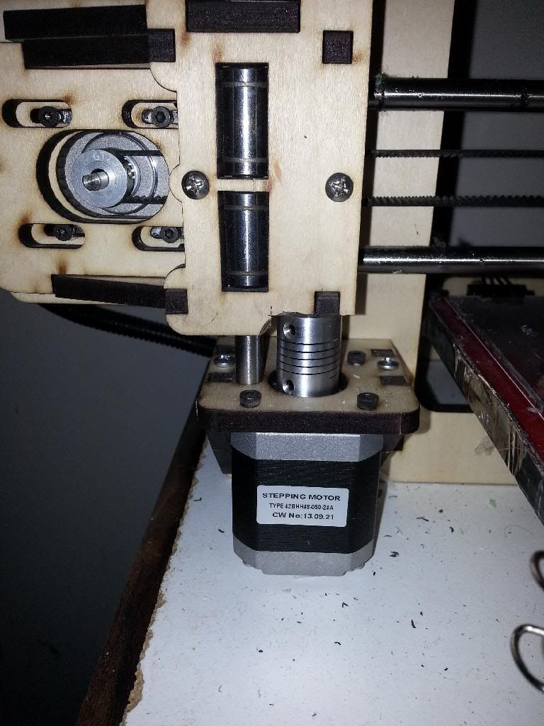
8) Make sure that there is clearance between the coupler and the Z-axis assembly as shown here.
Threaded Rod and Stepper Shaft Connected.jpg
9) Secure the couplers to the threaded rod by tightening the upper grub screws.
10) Pinch the couplers tight on the shafts and rods by tightening the Allen Key Head screws.
That's half the job done. Now you have to reset your Z = 0 point.
The couplers can foul on the Z-axis assembly as it comes back down to the Z=0 position it had when the tubing was joining the shafts and threaded rods. You will have to raise the print plate to give the couplers the clearance. The printer comes with four 6mm (1/4") lengths of nylon tubing spacers to fit between the hot bed and the Y-axis board. To give the required clearance after the couplers have been fitted, the original nylon tubing spacers have to be replaced with ones that are 12mm (1/2") long. This means sacrificing 6mm or 1/4" print height to have a more secure coupling between the shafts and rods. I used the tubing out of a liquid soap pump to get my 12mm spacers.
Fit the 12mm spacers at each corner of the heat bed. I suggest that you do not use a spring based bed leveling system. The security of the couplers will help prevent drifting of the Z = 0 point.
Now reset your Z-axis endstop following the procedure I have outlined in this thread:
http://3dprintboard.com/showthread.p...dstop-switches
Old Man EmuLast edited by old man emu; 03-13-2014 at 08:15 AM.
-
03-13-2014, 08:22 PM #2Engineer-in-Training
- Join Date
- Feb 2014
- Location
- CT
- Posts
- 345
Great post OME.
Just to add some DIY We added couplers and trimmed the plywood for clearance and also cut 10mm off the stepper motor shafts for the coupler clearance so no need to raise the bed.
-
03-15-2014, 06:04 PM #3Staff Engineer
- Join Date
- Oct 2013
- Location
- Narellan, New South Wales, Australia
- Posts
- 912
Your way does work, but my way is easier. I don't have to dis-assemble anything complex, and I only have to cut four pieces of nylon tubing to make new spacers. When did you last print to Z = 120?
OME
-
03-15-2014, 08:05 PM #4Engineer-in-Training
- Join Date
- Feb 2014
- Location
- CT
- Posts
- 345
I have a spring loaded leveling bed and did not want to raise the heat-bed due to heat-up time for the extra air space. Either will work.
 Originally Posted by old man emu


 Reply With Quote


QIDI Slicer "Plater" is...
04-12-2024, 02:21 AM in QiDi 3D Printer Forum